
Mastering Nylon Injection Molding: Critical Processing Parameters for PA6 and PA66
Essential Drying Protocols to Prevent Hydrolysis
Polyamides are hygroscopic and absorb moisture rapidly from the air. Uncontrolled moisture causes hydrolysis during processing, which permanently reduces molecular weight and mechanical strength.
Drying Specifications:
Insufficient drying leads to visible splay marks and brittle parts. Always verify moisture content is below 0.2% before starting production.
Precision Temperature Control Settings
Melt temperature directly impacts viscosity and fiber integrity in reinforced grades. Keep PA6 between 240°C and 260°C, while PA66 requires 260°C to 280°C.
Thermal Management Tips:
- Set nozzle temperatures 5°C lower than the front barrel zone to prevent drooling.
- Maintain mold temperatures between 60°C and 80°C to control crystallinity.
Higher mold temperatures improve surface finish but increase cycle time. Calculate cooling time based on the square of the part’s thickest section.
Injection Pressure and Speed Optimization
High injection speeds generate shear heat, which can degrade material at small gates. Balance speed to fill the cavity quickly without causing jetting or burning.
Pressure Phase Transition:
- Injection: Fill 95-98% of the cavity volume.
- Holding: Apply 50-70% of injection pressure to pack the part.
Proper backpressure ensures consistent melt density and color mixing. Switch to holding pressure immediately when the cavity is nearly full to minimize sink marks.
Comparative Analysis: Choosing Between Nylon 6 (PA6) and Nylon 66 (PA66)
Mechanical Properties and Performance Metrics
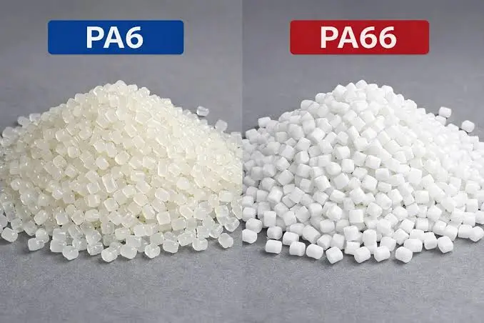
PA66 generally offers higher tensile strength and stiffness compared to PA6. Typical dry-as-molded tensile strength for PA66 is around 80-90 MPa, while PA6 ranges from 70-80 MPa.
- Impact Resistance: PA6 retains better toughness at low temperatures due to lower crystallinity.
- Fatigue Resistance: PA66 demonstrates superior resistance to cyclic loading in rigid applications.
PA6 exhibits superior abrasion resistance in high-wear scenarios like gears. Its lower friction coefficient reduces wear rates under sliding contact.
Thermal Stability and Heat Resistance
PA66 has a higher melting point of approximately 260°C compared to PA6 at 220°C. This allows PA66 to maintain structural integrity at higher operating temperatures.
- Heat Deflection Temperature (HDT): PA66 withstands higher loads at elevated temperatures.
- Continuous Use: PA66 is rated for continuous use up to 120-140°C, whereas PA6 is limited to 80-100°C.
Automotive under-hood components often require PA66 for thermal stability. PA6 may deform or lose mechanical properties in these high-heat environments.
Cost Efficiency and Supply Chain Considerations
PA6 is typically 10-20% cheaper than PA66 due to simpler manufacturing processes. Raw material price volatility affects PA66 more significantly due to adiponitrile supply constraints.
- Cycle Time: PA6 crystallizes faster, allowing shorter injection molding cycle times.
- Post-Processing: Both materials require moisture conditioning to stabilize dimensions.
Total cost of ownership favors PA6 for high-volume, less thermally demanding parts. PA66 justifies its higher cost in applications requiring strict thermal and mechanical performance.
Troubleshooting Common Defects in Nylon Injection Molding
Identifying and Eliminating Warpage
Nylon is semi-crystalline, leading to anisotropic shrinkage where flow-direction shrinkage differs from cross-flow direction. This differential often causes warping if cooling is uneven or internal stresses remain high.
- Shrinkage Rates: Typical flow direction shrinkage is 0.5-1.0%, while cross-flow can reach 1.5-2.5%.
- Crystallinity Impact: Higher mold temperatures increase crystallinity, raising overall shrinkage but improving dimensional stability over time.
To combat this, prioritize uniform cooling and strategic gate placement. Use conformal cooling channels where possible to maintain consistent mold surface temperatures within ±5°C.
Resolving Splay Marks and Surface Blemishes
Splay marks often stem from moisture or excessive shear heat. Nylon is hygroscopic and must be dried to below 0.2% moisture content before processing.
- Moisture Check: Dry nylon at 80-90°C for 4-6 hours using a dehumidifying dryer.
- Shear Control: Reduce injection speed if streaks appear near gates, indicating shear-induced degradation.
Distinguish between gas traps and material issues by inspecting mark location and pattern. Trapped air causes burns at the end of fill, while moisture causes random silver streaks.
Mitigating Sink Marks and Voids
Sink marks occur when thick sections cool slower than thin walls, causing surface depression. Voids form internally due to insufficient packing pressure during cooling.
- Packing Pressure: Increase hold pressure to 60-80% of injection pressure to compensate for shrinkage.
- Hold Time: Extend hold time until the gate freezes, typically 1-2 seconds per mm of wall thickness.
Design parts with uniform wall thicknesses to ensure even cooling. If thick sections are necessary, core out material to create uniform walls rather than solid masses.
The Impact of Glass Fiber Reinforcement on Nylon Molding
Changes in Shrinkage and Dimensional Stability
Glass fiber reinforcement significantly reduces overall shrinkage in nylon parts. Unfilled Nylon 6 typically shrinks 1.5–2.0%, while 30% glass-filled grades shrink only 0.2–0.5%.
Shrinkage is highly anisotropic, varying by flow direction.
- Parallel to flow: 0.2–0.4% shrinkage due to fiber alignment.
- Perpendicular to flow: 0.8–1.2% shrinkage as fibers restrict lateral contraction.
Enhanced Strength and Structural Integrity
Adding glass fibers drastically improves mechanical performance. A 30% glass-filled Nylon 66 offers tensile strength near 180 MPa, compared to 80 MPa for unfilled resin.
However, this gain comes with trade-offs in ductility and surface quality.
- Impact Strength: Decreases by up to 50% due to reduced polymer chain mobility.
- Surface Finish: “Fiber float” creates rough surfaces, often requiring higher gloss molds or post-processing.
Mold Design Adjustments for Abrasive Materials
Glass fibers act as abrasives, accelerating mold wear. Standard P20 steel wears quickly; use hardened H13 tool steel (48–52 HRC) for cores and cavities.
Protective coatings extend mold life in high-volume production.
- Coating Type: Titanium Nitride (TiN) or Nickel-Phosphorus.
- Benefit: Reduces friction and prevents material sticking in gates.
- Maintenance: Inspect venting channels every 10,000 cycles to prevent burn marks from trapped air.
Sourcing Reliable Custom Nylon Injection Molding Services
Evaluating Manufacturer Capabilities for Automotive and Industrial Parts
Automotive suppliers must hold IATF 16949 certification to ensure rigorous quality management standards. This credential validates the manufacturer’s ability to manage defect prevention and reduce variation in the supply chain.
- Quality Control: Implement Statistical Process Control (SPC) to monitor critical dimensions in real-time.
- Secondary Operations: Verify capabilities for ultrasonic welding and automated assembly to reduce post-processing costs.
High-volume production requires robust tooling designed for millions of cycles without significant wear. Manufacturers should demonstrate prototyping services that allow for rapid design validation before mass production begins.
Key Criteria for Selecting a Nylon Molding Partner
Select a partner with proven expertise in processing polyamides like PA6 and PA66. These materials require precise moisture control and specific melt temperatures between 260°C and 290°C to prevent degradation.
Transparency in pricing helps avoid hidden costs related to tooling modifications or material waste. Review case studies where the supplier successfully managed shrinkage rates typical of nylon, which range from 1.5% to 2.5%.
Ensuring Quality and Compliance in Custom Projects
Require full material traceability through certificates of analysis (COA) for every production batch. This documentation proves compliance with ISO and ASTM standards for mechanical and thermal properties.
- Inspection Methods: Use Coordinate Measuring Machines (CMM) for high-precision dimensional checks.
- Testing Protocols: Conduct tensile and impact tests to verify part performance under load.
Establish long-term partnership strategies that focus on continuous improvement and feedback loops. Regular audits of testing data ensure the manufacturer maintains consistent quality over the product lifecycle.