
Material Selection and Properties of PMMA for Injection Molding
Understanding PMMA (Acrylic) Characteristics
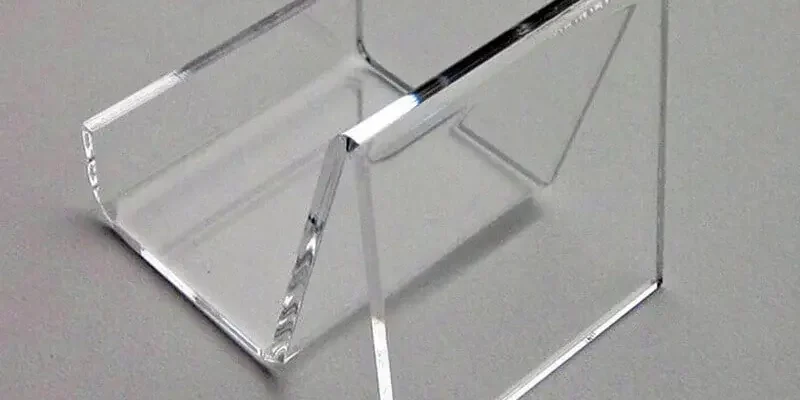
PMMA features a linear amorphous structure that enables exceptional optical clarity. It achieves light transmission rates up to 92%, surpassing standard glass.
- UV Resistance: Inherent stability prevents yellowing under prolonged sunlight exposure.
- Mechanical Limits: Impact resistance is lower than polycarbonate, requiring careful design to avoid stress cracking.
Thermal stability restricts processing windows, with heat deflection temperatures around 90–105°C. Engineers must manage melt temperatures between 230°C and 250°C to prevent degradation.
Comparing PMMA with Alternative Materials
PMMA offers significant weight savings compared to glass, being roughly half as dense. It provides superior shatter resistance while maintaining cost-effectiveness in high-volume molding.
| Material | Clarity | Scratch Resistance | Impact Strength |
|---|---|---|---|
| PMMA | Excellent (92%) | High | Low |
| Polycarbonate | Good (88%) | Low | Very High |
| Glass | Excellent | Very High | Brittle |
Choose PMMA over ABS or PS when surface aesthetics and transparency are critical. While polycarbonate offers better impact strength, PMMA requires less post-processing for scratch resistance.
Ideal Applications for PMMA Injection Molding
Automotive lighting relies on PMMA for tail lights and lenses due to its UV stability. Medical devices utilize this material for clear housings that withstand gamma sterilization without clouding.
- Consumer Electronics: Display panels benefit from high gloss and rigidity.
- Architectural Glazing: Signage uses PMMA for long-term weatherability and color retention.
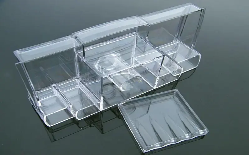
Luxury retail fixtures and cosmetic packaging leverage PMMA’s glass-like appearance at a lower production cost. This balance of aesthetics and manufacturability makes it ideal for premium consumer goods.
Optimizing Process Parameters for PMMA Injection Molding
Pre-Processing and Material Preparation
PMMA is highly hygroscopic and absorbs moisture from the air rapidly. Wet pellets cause hydrolysis during melting, leading to splay marks and reduced mechanical strength.
- Drying Specifications: Dry pellets at 80°C to 90°C for 4 to 6 hours.
- Moisture Limit: Ensure final moisture content is below 0.02% before processing.
Verify dryness using a calcium carbide tester or loss-on-drying analysis. Store dried material in sealed, desiccant-equipped hoppers to prevent re-absorption.
| Parameter | Recommended Value |
|---|---|
| Drying Temperature | 80°C – 90°C |
| Drying Time | 4 – 6 Hours |
| Max Moisture Content | 4000) |
Balance cooling time with dimensional stability requirements. Rapid cooling saves cycle time but may lock in residual stress.


LucasEdit Profile
Troubleshooting Common Defects in Acrylic Parts
Identifying and Resolving Visual Defects
Silver streaks often result from moisture or excessive shear heat. Dry PMMA resin to 0.02% moisture content at 80-90°C for 4-6 hours before processing.
| Defect | Primary Cause | Corrective Action |
|---|---|---|
| Silver Streaks | Moisture/Shear | Pre-dry resin; Reduce injection speed |
| Flow Lines | Low Melt Temp | Increase nozzle temp by 10-15°C |
Flow lines appear when the melt front cools too quickly. Raise the mold temperature to 60-80°C to maintain fluidity during filling.
Fixing Structural and Dimensional Issues
Warpage occurs due to uneven cooling rates across the part. Implement conformal cooling channels to ensure uniform heat extraction within ±5°C.
- Sink Marks: Increase holding pressure to 80-100 MPa to pack the cavity fully.
- Internal Stress: Avoid sharp corners; use radii of at least 0.5 times the wall thickness.
Cracking during ejection signals high residual stress. Optimize the cooling time to allow the part to solidify below its glass transition temperature (105°C) before release.
Achieving High Optical Clarity
Jetting creates visible snake-like patterns that ruin transparency. Use a larger gate diameter (min 1.5mm) to reduce entry velocity and promote laminar flow.
Post-molding annealing relieves internal stresses that cause haze. Heat parts to 80-90°C for 2-4 hours, then cool slowly at a rate of 10°C per hour.
| Process Step | Parameter | Benefit |
|---|---|---|
| Mold Polishing | Diamond paste (1 micron) | Removes micro-scratches |
| Annealing | 80°C for 3 hours | Improves light transmission |
Mold Design and DFM Guidelines for PMMA
Gate Design and Location Strategies
Select the correct gate type to manage flow and aesthetics. Fan gates are preferred for large parts to reduce shear stress, while submarine gates work well for automated degating.
- Gate Sizing: Keep gate thickness at 50-80% of the part wall thickness to prevent freezing.
- Shear Control: Limit injection speed to avoid excessive shear heating, which causes hazing or degradation.
Position gates away from high-visibility areas to hide vestiges. Balance multi-cavity molds using geometric symmetry or flow simulation data.
| Gate Type | Best Application | Key Benefit |
|---|---|---|
| Fan Gate | Large, flat panels | Low shear, uniform fill |
| Submarine | High-volume auto-degate | Hidden entry point |
| Pin Gate | Small, intricate parts | Precise location control |
Wall Thickness and Geometry Considerations
Maintain uniform wall thickness between 2.0 mm and 4.0 mm for optimal flow. Sudden changes cause flow marks and internal stresses in acrylic.
- Transitions: Use gradual tapers with a ratio of 1:3 when changing wall thickness.
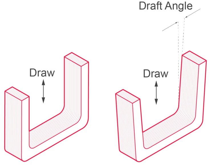
- Draft Angles: Apply minimum 1° draft per side to prevent scratching during ejection. Note that for textured surfaces, a general rule of thumb is $1^{\circ} \sim 1.5^{\circ}$ of draft angle for every $0.025 \mathrm{~mm}$ of texture depth.
Design ribs to be 50-60% of the main wall thickness. This prevents sink marks while maintaining structural rigidity.
| Feature | Recommended Dimension | Purpose |
|---|---|---|
| Wall Thickness | 2.0 – 4.0 mm | Consistent cooling |
| Rib Thickness | 50-60% of wall | Avoid sink marks |
| Draft Angle | ≥ 1° per side | Easy ejection |
Venting and Surface Finish Requirements
Cut vents to a depth of 0.01-0.02 mm to allow air escape without flash. Place vents at the end of fill paths and near weld lines.
- Surface Standards: Use SPI A1/A2 finishes for optical clarity. Ideally, surface irregularities should be gentle hills and valleys rather than sharp scratches to facilitate demolding, especially for high-modulus glassy amorphous polymers like PMMA.
- Matte Finishes: Select SPI C1-C3 for non-visible structural components.
Use hardened steel (HRC 50+) for molds processing glass-filled PMMA. This resists abrasion and extends mold life.
| Requirement | Specification | Reason |
|---|---|---|
| Vent Depth | 0.01 – 0.02 mm | Prevents flash |
| Optical Finish | SPI A1/A2 | Maximum transparency |
| Mold Steel | HRC 50+ Hardened | Resists abrasion |
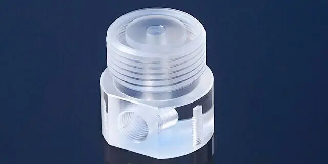
Place ejector pins on non-critical surfaces to avoid visible marks. Ensure pin faces are polished to match the cavity finish if contact is unavoidable. For protruding metal thread inserts in the mold, a shoulder should be provided to seal off any thermoplastic flash around the insert threads during molding.
Sourcing and Manufacturing Services for PMMA Parts
Evaluating Potential Manufacturing Partners
Select a partner with ISO 9001 or IATF 16949 certification to ensure consistent quality management. Verify their experience with optical-grade PMMA, specifically their ability to maintain haze levels below 1% and achieve tight tolerances of ±0.05 mm.
- Clean Room Standards: Look for ISO Class 7 or 8 environments to prevent dust inclusion in transparent parts.
- Inspection Capabilities: Ensure they use automated optical inspection (AOI) systems for detecting surface defects like flow marks or scratches.
Review case studies that demonstrate successful handling of high-transparency acrylic projects. Ask for specific examples of how they managed warpage control in large, flat panels.
Understanding Lead Times and Production Scalability
Expect a timeline of 4–6 weeks for rapid tooling prototypes and 8–12 weeks for hardened production molds. Scaling from low-volume runs to mass production requires careful planning of raw material reserves to avoid supply chain bottlenecks.
| Phase | Typical Duration | Key Consideration |
|---|---|---|
| Quoting | 3–5 Days | Detailed 3D data reduces iteration time. |
| Tooling | 4–12 Weeks | Aluminum molds for speed; steel for longevity. |
| First Article | 1–2 Weeks | Validate dimensions against CAD models. |
Secure bulk resin contracts early to mitigate price volatility in the acrylic market. This strategy ensures material availability during peak production cycles.
Request for Quote (RFQ) Best Practices
Include precise 3D STEP files, specified PMMA grade (e.g., Plexiglas VSG), and annual volume forecasts in your RFQ. Clearly define critical cosmetic areas using visual aid samples to set acceptable standards for scratches and inclusions.
- Secondary Operations: Specify requirements for flame polishing, UV bonding, or screen printing upfront.
- Pricing Structure: Request separate costs for tooling amortization and per-unit pricing at various volume breaks.
Negotiate pricing based on total cost of ownership rather than just unit price. Clarify who owns the tooling intellectual property to avoid future manufacturing restrictions.