
Identifying Top Heat-Resistant Plastic Materials for Engineering Applications
Key High-Performance Thermoplastics Overview
High-temperature polymers maintain structural integrity above 150°C. They replace metals in aerospace and automotive sectors to reduce weight.
PEEK offers continuous use up to 260°C with excellent chemical resistance. It serves as the benchmark for demanding mechanical applications.
| Material | Continuous Use Temp (°C) | Key Advantage |
|---|---|---|
| PEEK | 260 | Mechanical strength |
| PEI | 170 | Ease of processing |
| PTFE | 260 | Chemical inertness |
PEI balances thermal stability at 170°C with easier injection molding. It provides high rigidity without the extreme processing costs of PEEK.
PTFE withstands 260°C while resisting nearly all industrial chemicals. Its low friction coefficient makes it ideal for seals and bearings.
PPS, PI, and PAI fill niche roles requiring specific stiffness or heat spikes. PPS handles 220°C continuously, while PI survives short peaks above 300°C.
Engineers must distinguish between continuous ratings and short-term peaks. Exceeding continuous limits causes irreversible molecular degradation over time.
Criteria for Selecting Heat-Resistant Plastics
Continuous high temperature refers to long-term exposure without property loss. Industry standards typically define this as 20,000 hours of service life.
Glass Transition Temperature (Tg) marks the shift from rigid to rubbery states. Melting Point (Tm) indicates the temperature where crystalline structures collapse.
- Tg: Critical for amorphous plastics like PEI.
- Tm: Critical for semi-crystalline plastics like PEEK.
Thermal aging reduces tensile strength and impact resistance over time. Accelerated aging tests predict material lifespan under constant heat stress.
Chemical compatibility prevents swelling or cracking in harsh environments. Mechanical loads must remain within limits as heat softens the polymer matrix.
Electrical insulation properties often degrade near the material’s Tg. Designers must verify dielectric strength at maximum operating temperatures.
Comparative Analysis: Thermal Limits, Mechanical Strength, and Cost
Thermal Performance Metrics Comparison
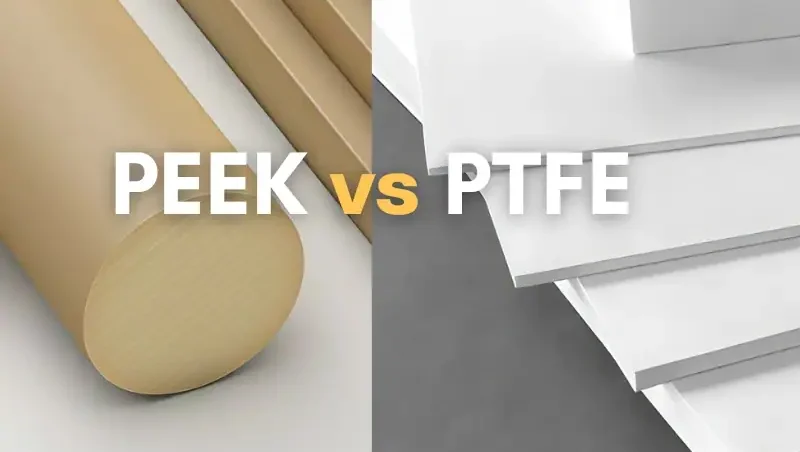
High-performance plastics exhibit distinct thermal ceilings that dictate their application scope. PEEK sustains continuous use up to 250°C, while PEI limits operation to roughly 170°C.
PTFE offers exceptional stability up to 260°C but lacks structural rigidity. Selecting the right polymer requires matching these limits to peak operating conditions.
| Material | Max Continuous Temp (°C) | HDT @ 1.8 MPa (°C) |
|---|---|---|
| PEEK | 250 | 160 |
| PEI (Ultem) | 170 | 200 |
| PTFE | 260 | N/A (Softens) |
Heat Deflection Temperature (HDT) varies significantly under load. PEI maintains higher stiffness at moderate temperatures compared to unfilled PEEK.
Thermal conductivity remains low for most polymers, acting as insulators. Unfilled PEEK has a conductivity of approximately 0.25 W/m·K.
Adding fillers drastically alters thermal behavior. Carbon fiber increases conductivity to 0.5–1.0 W/m·K, aiding heat dissipation.
Glass fiber improves dimensional stability but does not significantly boost conductivity. Engineers must balance insulation needs with heat management requirements.
Mechanical Strength and Durability Under Heat
Tensile strength degrades as temperatures approach the glass transition point. PEEK retains about 50% of its room temperature modulus at 150°C.
PEI shows sharper declines in stiffness above 150°C. Designers must apply safety factors when calculating load-bearing capacity at elevated temperatures.
Creep resistance is critical for long-term structural integrity. PEEK exhibits superior resistance to cold flow under constant stress compared to PTFE.
PTFE suffers from significant creep even at room temperature. This makes it unsuitable for high-load static applications without specialized modifications.
Wear resistance depends heavily on the friction coefficient. PTFE offers the lowest coefficient (0.05–0.10), ideal for sliding interfaces.
PEEK provides better abrasion resistance for dynamic loads. Adding carbon fiber further reduces wear rates in high-speed bearing applications.
Impact strength often decreases as materials become brittle at low temperatures or soft at high temperatures. PEEK maintains ductility better than PEI across a wider thermal range.
PEI can become prone to cracking under sudden impact at sub-zero temperatures. Testing specific grades for toughness is essential for dynamic environments.
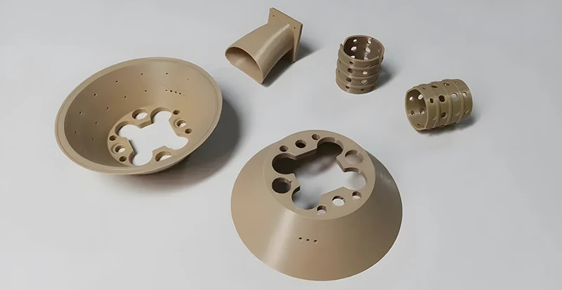
Cost-Benefit Analysis and Material Availability
Raw material costs vary exponentially among high-performance polymers. PEEK typically costs $80–$120 per kg, significantly higher than PEI at $30–$50 per kg.
PTFE ranges from $20–$40 per kg but requires specialized processing. Standard engineering plastics like Nylon remain under $5 per kg.
| Material | Approx. Cost ($/kg) | Primary Cost Driver |
|---|---|---|
| PEEK | 80–120 | Synthesis complexity |
| PEI | 30–50 | Monomer cost |
| PTFE | 20–40 | Processing difficulty |
Processing expenses add to the total manufacturing budget. PEEK requires high melt temperatures (340–400°C), demanding robust injection molding machines.
PEI processes at lower temperatures (330–370°C) but is sensitive to moisture. Strict drying protocols are necessary to prevent hydrolysis and part degradation.
Machining PTFE is cost-effective for prototypes but challenging for mass production. Its softness leads to tooling wear and dimensional inconsistencies.
Lifecycle costs often justify the higher initial investment in PEEK. Its durability reduces maintenance frequency and replacement parts in harsh environments.
PEI offers a balanced option for moderate heat applications. It provides adequate performance where PEEK’s extreme capabilities are unnecessary.
Supply chain volatility affects specialty polymers more than commodity plastics. Lead times for PEEK can extend to 8–12 weeks during high demand.
Securing multiple suppliers mitigates risk for critical components. Early engagement with resin distributors ensures material availability for production schedules.
Manufacturing Prototypes: 3D Printing and CNC Machining Options
High-Temperature 3D Printing Technologies and Materials
High-performance filaments like PEEK, PEI, and PEKK require specific thermal environments to succeed.
Printers must maintain chamber temperatures above 120°C to prevent warping and ensure layer bonding.
Nozzle temperatures typically range from 360°C to 450°C depending on the polymer grade.
Heated build plates should reach at least 140°C to secure strong bed adhesion during long prints.
| Material | Nozzle Temp (°C) | Bed Temp (°C) | Chamber Temp (°C) |
|---|---|---|---|
| PEEK | 400–450 | 140–160 | >120 |
| PEI (ULTEM) | 360–400 | 130–150 | >100 |
| PEKK | 380–420 | 130–150 | >110 |
Selective Laser Sintering (SLS) offers isotropic strength for heat-resistant nylon and PEEK powders.
This method eliminates support structures, allowing complex geometries without post-print removal risks.
Post-processing annealing is critical to control crystallinity and relieve internal stresses.
Proper annealing cycles can increase the heat deflection temperature by up to 20%.
Common challenges include poor layer adhesion due to rapid cooling in open environments.
Warpage remains a primary failure mode if thermal gradients are not strictly managed.
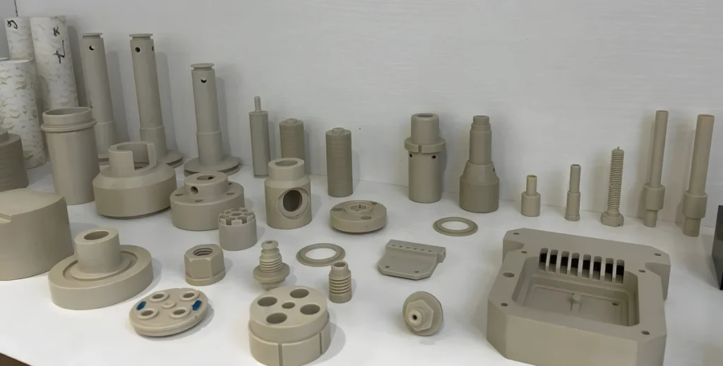
CNC Machining Heat-Resistant Plastics for Precision Prototypes
PEEK and PEI machine well with sharp carbide tools, while PTFE requires specialized geometry.
Use polished flutes and high rake angles to prevent material galling and buildup on cutting edges.
Maintain low cutting speeds between 100–200 m/min to minimize heat generation.
High feeds help shear the material cleanly rather than rubbing, which causes melting.
Coolant usage varies; air blasts are preferred for PEEK to avoid moisture absorption.
PEI can tolerate mist coolants, but flood cooling may lead to micro-cracking in stressed parts.
| Material | Tool Type | Recommended Speed (m/min) | Coolant Strategy |
|---|---|---|---|
| PEEK | Carbide, Polished | 100–150 | Air Blast |
| PEI | Carbide, Sharp | 120–180 | Mist or Air |
| PTFE | HSS/Carbide, High Rake | 80–120 | Dry/Air |
Heat generation during machining must be controlled to prevent thermal degradation of the polymer.
Excessive heat lowers mechanical properties and causes dimensional instability in the final part.
Achieving tight tolerances under ±0.05 mm requires stable fixturing and minimal clamping force.
Soft jaws or vacuum fixtures prevent deformation of high-temp plastics during milling operations.
Surface finishes below Ra 1.6 µm are achievable with fine step-overs and sharp tooling.
Post-machining polishing may be needed for sealing surfaces or aesthetic requirements.
CNC machining generally offers faster turnaround for single prototypes compared to high-temp 3D printing.
However, additive manufacturing becomes cost-effective for complex, low-volume batches requiring no tooling.
Choose CNC for superior mechanical isotropy and precise feature definition.
Select 3D printing for intricate internal channels or when lead time for tooling is prohibitive.
Lightweight, Corrosion-Resistant Alternatives to Metal in Extreme Heat
Advantages of Plastics Over Metals in High-Temperature Applications
Weight Reduction Benefits
High-performance plastics offer significant density advantages over traditional metals. This reduction directly lowers inertia and energy consumption in moving assemblies.
| Material | Typical Density (g/cm³) | Weight Savings vs. Steel |
|---|---|---|
| Steel | 7.85 | Baseline |
| Aluminum | 2.70 | ~65% |
| PEEK | 1.32 | ~83% |
| PAI (Torlon) | 1.41 | ~82% |
Engineers can achieve up to 80% weight savings by switching from steel to polymers like PEEK. This is critical for aerospace and portable equipment where every gram counts.
Inherent Corrosion and Chemical Resistance
Plastics do not oxidize or rust when exposed to moisture and harsh chemicals. This eliminates the need for protective coatings or regular maintenance schedules.
- Resistant to acids, bases, and solvents at elevated temperatures.
- No galvanic corrosion risks when paired with dissimilar metals.
Materials like PVDF and PTFE maintain integrity in pH extremes where stainless steel might pit. This ensures longer component life in chemical processing environments.
Thermal Insulation Properties
Polymers have significantly lower thermal conductivity than metals. This property protects sensitive electronics and reduces heat loss in fluid systems.
| Material | Thermal Conductivity (W/m·K) |
|---|---|
| Aluminum | 205 |
| Stainless Steel | 16 |
| PEEK | 0.25 |
| PTFE | 0.25 |
Using plastic housings prevents heat soak into adjacent components. This reduces the need for additional thermal barriers or cooling systems.
Design Flexibility
Injection molding allows for complex geometries that are impossible or costly with metal machining. Features like internal channels and undercuts can be molded in a single step.
- Consolidates multiple metal parts into one plastic component.
- Reduces assembly time and potential leak points.
This integration lowers overall manufacturing costs and simplifies supply chains. It also enables optimized flow paths for fluids and gases.
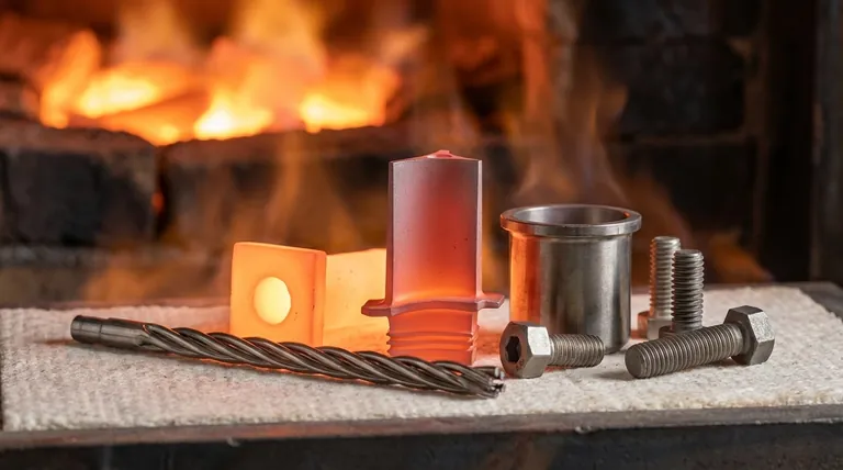
Case Studies: Replacing Metal Components with High-Temp Plastics
Aerospace Applications
Aircraft manufacturers use PEI and PPS for interior brackets and ducting. These materials meet strict flame, smoke, and toxicity standards.
- Reduces fuel consumption through lower structural weight.
- Withstands continuous exposure to 150°C–170°C.
Lightweight ducts resist vibration fatigue better than thin-gauge aluminum. This improves reliability in high-vibration engine zones.
Automotive Under-the-Hood Solutions
Modern engines operate at higher temperatures, requiring robust sensor housings. PPA and PCT replace aluminum in water pump impellers and thermostat housings.
| Component | Traditional Material | Plastic Alternative | Max Temp (°C) |
|---|---|---|---|
| Sensor Housing | Aluminum | PPS | 200 |
| Connector | Brass | PPA | 180 |
| Pump Impeller | Cast Iron | PCT | 190 |
These plastics resist glycol-based coolants and oil mist without degrading. They also provide electrical insulation for integrated sensors.
Oil and Gas Industry
Downhole tools face extreme pressure and corrosive brines. Vespel and PEEK seals outperform metal in these aggressive environments.
- Maintains sealing force at temperatures up to 250°C.
- Resists H₂S and CO₂ corrosion common in sour gas wells.
Plastic valve components reduce wear on mating metal surfaces. This extends maintenance intervals and reduces downtime.
Electronics and Semiconductor
Wafer carriers require ultra-pure materials to prevent contamination. PFA and PTFE are standard for their low particle generation.
- Withstands repeated cleaning cycles in acidic baths.
- Provides excellent dielectric properties for testing fixtures.
Metal alternatives risk leaching ions that damage microchips. Plastics ensure process purity and yield consistency.
Selection Guide for Metal Replacement
Assessing Load-Bearing Requirements
Plastics have lower modulus and strength than metals. Engineers must analyze static and dynamic loads carefully before substitution.
- Use glass or carbon fiber reinforcement to boost stiffness.
- Account for creep deformation under long-term load.
Finite element analysis (FEA) helps predict stress concentrations. Avoid sharp corners to prevent premature failure in polymer parts.
Addressing Thermal Expansion Differences
Plastics expand 5–10 times more than metals when heated. This mismatch can cause joint failure or binding in tight tolerances.
| Material | Coefficient of Thermal Expansion (µm/m·°C) |
|---|---|
| Steel | 11–13 |
| Aluminum | 23–24 |
| PEEK | 45–50 |
| Unfilled Nylon | 80–100 |
Design slots instead of round holes for mounting points. This allows the plastic part to expand without generating excessive stress.
Joining and Assembly Techniques
If components require periodic disassembly, consider using metal inserts for connections. Most inserts should be installed using ultrasonic or heating methods to minimize residual stress. Common insert types include molded-in and press-fit variants.
For through holes and tapered holes, proper insert installation is critical to ensure alignment and load distribution. In mold design, protruding metal threaded inserts should feature a shoulder to seal off any thermoplastic flash around the threads during the molding process.
Standard welding methods often fail with high-temp plastics. Specialized techniques ensure strong and reliable assemblies.
- Ultrasonic Welding: Effective for thermoplastics like PPS and PEI.
- Mechanical Fastening: Use wide-head screws to distribute load.
- Adhesives: Select epoxies rated for the operating temperature range.
Overmolding plastic onto metal inserts creates secure hybrid parts. Ensure proper surface preparation for adhesion.
Long-Term Reliability Testing and Validation Strategies
Accelerated aging tests predict material performance over time. Exposure to heat and chemicals reveals potential degradation modes.
- Conduct tensile tests after thermal aging at max temperature.
- Monitor dimensional stability during thermal cycling.
Validate designs against industry standards like ISO 11403. Real-world pilot runs confirm laboratory findings before full production.
Thermosets vs. Thermoplastics: Performance in High-Heat Environments
Fundamental Differences in Structure and Behavior
Thermosets form irreversible cross-linked networks during curing. This structure prevents the material from melting when reheated.
Thermoplastics consist of linear or branched polymer chains. They soften and flow when heated above their glass transition temperature.
| Feature | Thermosets | Thermoplastics |
|---|---|---|
| Molecular Bond | Covalent cross-links | Weak intermolecular forces |
| Heat Response | Chars or burns | Melts and reshapes |
| Recyclability | Low (chemical recycling only) | High (mechanical recycling) |
Processing methods differ significantly due to these structural properties. Thermosets typically use compression molding or resin transfer molding.
Thermoplastics are processed via injection molding or extrusion. These methods allow for faster cycle times and easier automation.
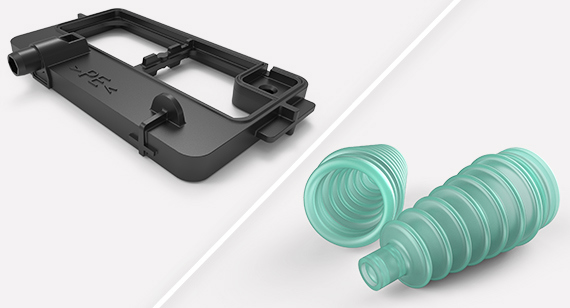
Performance Comparison in Extreme Heat
Thermal stability is measured by decomposition temperature and char yield. Thermosets like phenolics often exhibit higher char yields at 600°C.
High-performance thermoplastics such as PEEK maintain stability up to 250°C continuous use. Beyond this, they risk rapid mechanical failure.
Mechanical property retention varies widely at peak temperatures. Thermosets retain stiffness better near their degradation point.
Thermoplastics experience a sharp drop in modulus above their glass transition temperature ($T_g$). Designers must account for this loss in load-bearing capacity.
Chemical resistance profiles depend on the specific polymer chemistry. Epoxies offer superior resistance to solvents but may degrade under UV exposure.
PEEK and Polyimide (PI) provide excellent chemical and thermal resistance. However, they come at a significantly higher raw material cost.
Choosing the Right Polymer Type for Your Application
Select thermosets for applications involving high static loads and extreme heat. They are ideal for engine components and electrical insulators.
These materials offer lower raw material costs. However, tooling costs can be higher due to longer cure cycles.
Choose thermoplastics when impact resistance and recyclability are priorities. They suit complex geometries requiring tight tolerances.
Injection molding allows for high-volume production efficiency. Cycle times are typically seconds rather than minutes.
Hybrid solutions combine thermoplastic toughness with thermoset rigidity. Thermoplastic composites reinforced with thermoset matrices are emerging.
Future trends show high-performance thermoplastics challenging traditional thermosets. Advances in carbon fiber reinforcement improve their heat deflection temperatures.