Design Guidelines for Strong Injection Molded Threads
Fundamental Geometry and Thread Types
For plastics, choose threads with the biggest diameter, a nearly flat load face, and deep cuts. Thread choice matters a lot. Never use tapered (pipe) threads in plastics.
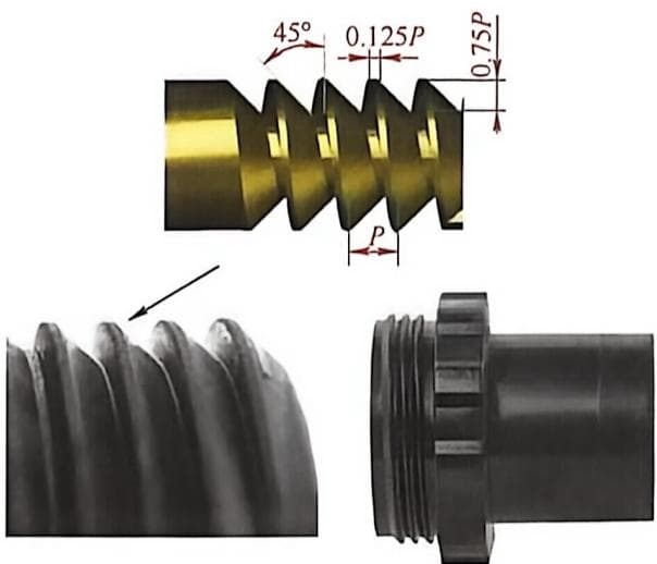
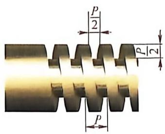
1-Buttress Threads: The preferred choice for thermoplastic applications subjected to unidirectional loads. Since the bearing surface is nearly perpendicular to the screw axis, the load is transmitted almost entirely axially rather than radially. For thermoplastic products, it is recommended to use the largest possible root radius, typically between $0.035P$ and $0.070P$.
2-Rectangular Threads: Used for mechanical transmission (e.g., jack screws) due to high efficiency. However, they are not recommended for thermoplastics because stress concentration at the thread root can lead to shear failure.
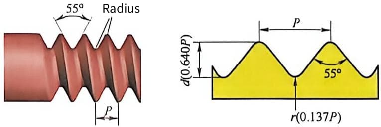
3-Whitworth Threads: Although being phased out in some industries, Whitworth threads are an excellent design for thermoplastics. This thread form features a large root radius of $0.137P$, which significantly reduces stress concentration effects.
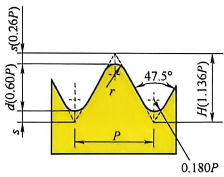
4-Inch standard thread: British Standards recommends this thread for diameters under 1/4 inch. This form works great for thermoplastics, with a 47.5° angle and 0.180P root radius.
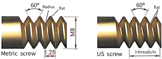
5-Metric & American Standard Threads: The most common in design. When connecting thermoplastics to metal, only use coarse threads to avoid damaging the plastic threads.
6-Trapezoidal Threads: For power transmission. Metric types have a 30° angle, inch types 29°. Sharp corners at the flat root cause high stress concentration, and hoop stress builds up at the weakest point, causing failure. Don’t use this thread with thermoplastics.
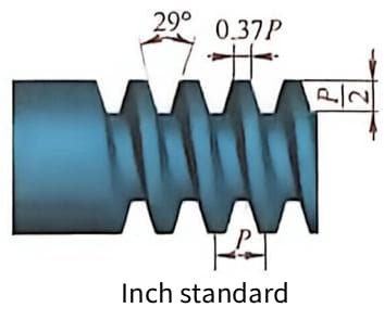
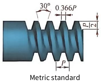
Thread Size Structure Optimization
Do not extend threads to the very end of the feature. This avoids creating thin, feather-like thread ends that are prone to cross-threading.
Use the maximum allowable radius at the major diameter and minor diameter of the thread.
To facilitate forming and prevent cross‑threading, limit the thread pitch to 0.8mm or above.
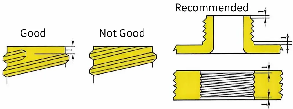
- Safety Factor: Apply a factor of 2–3 for dynamic loads.
Mold Mechanisms for Demolding Threaded Undercuts
Rotational Unscrewing Devices
External threads are formed automatically using the parting line of a two-plate mold or by angle pins and sliders.
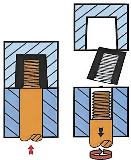
Internal threads are formed using automatic unscrewing devices. The core moves forward for injection molding and then retracts to unscrew the core from the molded product for demolding.
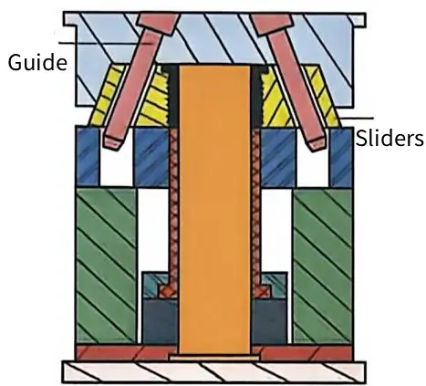
Collapsible Cores and Segmented Tools
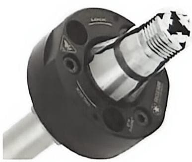
Collapsible cores represent a significant breakthrough in injection molding for thermoplastic products with internal threads, undercuts, and protrusions. This mold type has only three moving parts and uses traditional mold movement methods.
For traditional internal threads, the automatic operation of collapsible core molds can shorten the injection molding cycle by 30%.
Manual and Semi-Automated Solutions
Figure below shows a thread insert mold and its molding steps. The insert is manually unscrewed for further use during the molding process.
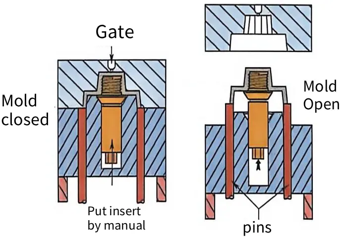
Hand-loaded inserts are cost-effective for prototype runs or volumes under 1,000 units. They eliminate complex mold mechanics but rely heavily on operator consistency. Designing for manual unscrewing requires accessible part geometry and adequate grip features. Operators remove parts post-molding, which increases labor costs per unit.
Semi-automatic slides offer a middle ground between cost and efficiency. They reduce cycle time compared to manual methods but lack the speed of full automation. Simple lifters are suitable when thread depth is shallow and draft angles permit. Choose them over unscrewing mechanisms when production volume does not justify high tooling investment.
Alternatives to Molded Threads for Cost and Complexity Reduction
Self-Tapping and Forming Screws
Select the correct screw type based on material brittleness. Thread-forming screws displace plastic without removing material, which is ideal for ductile resins like ABS or Polycarbonate. Thread-cutting screws remove material and generate chips, making them suitable for brittle plastics like filled Nylon to prevent stress cracking.
Threaded Inserts and Ultrasonic Welding
Choose insert installation methods based on production volume and strength requirements. Ultrasonic inserts offer high pull-out strength by melting the surrounding plastic for a secure lock. Press-fit inserts are faster to install but generally provide lower torque-out resistance.
Eliminate undercuts in the mold design by using inserts instead of molded threads. This simplifies the tooling structure by removing the need for rotating cores or collapsible cores. Simplified tools reduce maintenance costs and decrease the risk of mechanical failure during high-speed cycling.
Snap-Fits and Bayonet Mounts
Replace threaded connections with snap-fits to significantly reduce cycle times. Snaps eliminate the rotational time required for screw driving or nut tightening. This change can reduce assembly time per unit by several seconds, which adds up in high-volume manufacturing.
Evaluate user experience against the perceived quality of threaded fasteners. Snaps and bayonets feel faster but may lack the premium tactile feedback of a tightened screw. Ensure the break-away torque or snap force is calibrated to feel secure without requiring excessive user effort.
Material Selection for Durability and Ejection Performance
High-Strength Engineering Thermoplastics
PEEK, PPS, and Polycarbonate offer superior mechanical properties for high-torque applications. Their high heat deflection temperatures prevent thread deformation during ejection.
- PEEK: Withstands continuous use up to 250°C with excellent chemical resistance.
- PPS: Provides rigid structural integrity with minimal creep under load.
Nylon (PA) exhibits higher fatigue resistance than Acetal (POM) in dynamic loading scenarios. However, POM offers better dimensional stability due to lower moisture absorption.
| Material | Tensile Strength (MPa) | Fatigue Resistance | Moisture Sensitivity |
|---|---|---|---|
| Nylon 6/6 | ~80 | High | High |
| Acetal (POM) | ~65 | Moderate | Low |
Glass-filled compounds significantly increase thread stripping resistance by reinforcing the polymer matrix. A 30% glass fiber content is standard for maximizing tensile modulus. Be cautious of increased abrasion on mold surfaces when using filled materials. Hardened steel molds with HRC 52+ hardness are required to withstand wear.
Materials Prone to Stripping and Damage
Soft materials like LDPE and TPE lack the rigidity needed for standalone threaded features. They deform easily under torque, leading to immediate stripping.
- Use metal inserts to transfer load away from the soft polymer.
- Design larger boss diameters to distribute stress over a wider area.
Hygroscopic materials like Nylon swell when absorbing moisture from the environment. This dimensional change can tighten thread fits beyond acceptable tolerances. Always account for a 0.5% to 1.5% dimensional increase in humid conditions. Pre-drying parts before assembly ensures consistent fitment.
Unmodified Polystyrene and SAN are brittle and prone to cracking during unscrewing. Their low impact strength makes them unsuitable for snap-fit or threaded ejection. Avoid these materials for threads requiring more than minimal assembly force. Consider blending with rubber modifiers if transparency allows.
Friction and Wear Considerations
Acetal and UHMWPE possess naturally low coefficients of friction, ideal for self-lubricating threads. This reduces the torque required for ejection and assembly.
- Acetal (POM): Coefficient of friction ~0.2 against steel.
- UHMWPE: Offers superior wear resistance but lower stiffness.
Frequent assembly cycles demand materials with high abrasion resistance. Additives like PTFE or silicone can further reduce surface friction. Material shrinkage directly impacts the clearance between male and female threads. High-shrink materials require larger mold allowances to maintain fit.
| Material | Typical Shrinkage (%) | Recommended Clearance |
|---|---|---|
| Acetal | 2.0 – 2.5% | Loose Fit |
| Polycarbonate | 0.5 – 0.7% | Standard Fit |
Mismatched mating materials can lead to galling or cold welding under pressure. Pair hard polymers with softer counterparts to minimize adhesive wear. Ensure dissimilar materials have compatible thermal expansion rates. This prevents binding during temperature fluctuations in end-use environments.
Manufacturing Implications: Costs, Cycle Times, and Automation
Cost Analysis: Tooling vs. Unit Price
Standard injection molds are significantly cheaper than those with unscrewing mechanisms. Complex actuators and gear systems can double or triple the initial tooling investment.
| Mold Type | Estimated Tooling Cost Factor | Best For |
|---|---|---|
| Standard | 1x (Base) | Low volume, simple geometry |
| Unscrewing | 2.5x – 4x | High volume, integrated threads |
Break-even analysis is critical for justifying automated demolding costs. High-volume runs typically offset higher tooling costs after 50,000 to 100,000 cycles. Rotating mold components require frequent maintenance to prevent wear and seizure. Budget for annual servicing costs, which can range from 5% to 10% of the tooling price. Manual insert molding remains cost-effective for production volumes under 5,000 units. This approach avoids complex tooling but increases labor costs per unit.
Cycle Time Efficiency and Production Throughput
Unscrewing mechanisms add 3 to 8 seconds to the mold open time. This extension directly increases the overall cycle duration compared to standard ejection. Optimized cooling channels near threaded features reduce thermal resistance. Target a coolant temperature of 10°C to 15°C to solidify threads faster without warping.
Fully automatic unscrewing offers higher throughput than secondary tapping operations. Secondary operations often create bottlenecks, limiting output to 60% of molded capacity. Multi-cavity molds with unscrewing features require higher clamp tonnage. Ensure the injection molding machine has 20% extra tonnage capacity to handle uneven forces.
Strategic Decision Making for Threaded Parts
Outsource threading as a secondary operation when annual volumes are below 20,000 units. This strategy reduces upfront capital expenditure and simplifies mold design. Evaluate Total Cost of Ownership (TCO) by including labor, energy, and maintenance. Automated lines often show a 15% lower TCO over five years for high-volume parts.
Mold downtime due to unscrewing failure can halt entire production lines. Implement predictive maintenance schedules to monitor gear wear and motor performance. Transitioning from molded threads to metal inserts can reduce scrap rates by 10%. Inserts provide superior torque resistance and eliminate thread stripping risks in soft plastics.