
Design Parameters for Injection Molded Living Hinges
Critical Dimensional Guidelines
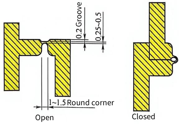
The hinge thickness is the primary determinant of fatigue life and flexibility. Industry standards typically recommend a thickness between 0.25mm and 0.50mm for polypropylene (PP).
Thinner sections below 0.25mm risk premature failure due to material degradation or flow stagnation. Thicker sections above 0.50mm induce excessive bending stress, leading to white stress marks and cracking.
| Parameter | Recommended Range | Engineering Rationale |
|---|---|---|
| Hinge Thickness | 0.25mm – 0.50mm | Balances flexibility, flow capacity, and molecular orientation |
| Hinge Length | 0.5mm – 1.0mm | Distributes strain over a larger area |
Hinge length must correlate with the required range of motion. A longer hinge distributes strain more effectively across the polymer chains.
Avoid sharp internal corners at the hinge base to prevent stress concentrators. Sharp corners cause the “notch effect,” a primary cause of plastic part failure, by concentrating stress. Additionally, narrow hinges with sharp corners create significant obstacles to melt flow in the mold. Using generous radii ensures smooth material flow, minimizes flow obstacles.
Another critical design consideration relates to the notch effect on the back of the hinge. If the hinge back is formed by a flat plane, bending causes the material to form a sharp, high-stress crease, acting as a notch that significantly increases the likelihood of failure. To mitigate this, provide a shallow groove on the back of the hinge.
Material Selection Criteria
Polypropylene (PP) remains the industry standard for living hinges due to its semi-crystalline structure. It is the preferred material for hinges requiring robustness and high cycle counts due to its excellent resistance to bending fatigue.
Gate Placement and Flow Dynamics
Gate placement dictates molecular orientation, which is vital for hinge durability. The most critical feature of injection molding process design for living hinges is that the melt flow during mold filling must pass through the hinge, not along it.
When melt flows through the thin hinge section, long-chain polymer molecules align in the direction of flow. This alignment makes the injected part extremely strong in the flow direction but relatively weak in the direction perpendicular to the flow. If the melt flow proceeds along the hinge, the stress on the hinge will exploit this weakness, causing the hinge to fracture during use. Therefore, the gate must be positioned so that melt flow travels perpendicular to the hinge axis (through the thickness), ensuring the molecular orientation reinforces the hinge against bending stresses.
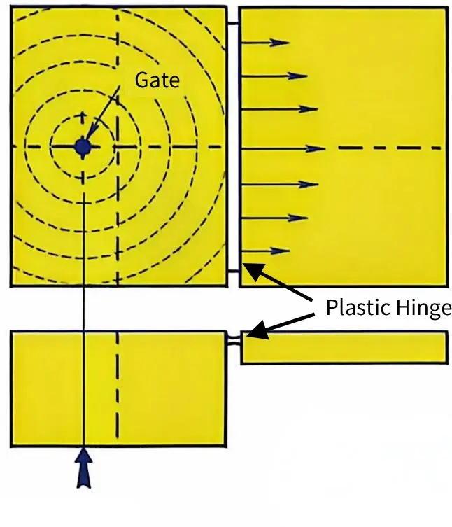
Edge gating is often preferred for direct control over flow direction. Submarine gates can be used but require careful validation to avoid cross-flow turbulence.
| Gating Strategy | Flow Alignment | Risk Factor |
|---|---|---|
| Edge Gate | Through hinge (Perpendicular to axis) | Low if centered |
| Submarine Gate | Variable | Moderate shear stress |
| Pin Gate | Perpendicular (Avoid if flow is parallel) | High weld line risk |
Weld lines across the hinge area create weak points prone to immediate failure. Mold design must ensure single-direction flow to eliminate knit lines in the hinge zone.
Runner systems should maintain uniform pressure to prevent differential cooling. Balanced runners help achieve consistent molecular orientation across multiple cavities.
Living Hinges vs. Traditional Mechanical Hinges: A Comparative Analysis
Advantages of Injection Molded Living Hinges
Living hinges significantly reduce manufacturing costs by eliminating secondary assembly steps. This consolidation removes the need for separate pins, screws, or multi-part assemblies, streamlining production lines.
Part count reduction directly lowers overall product weight and inventory complexity. Engineers can integrate the hinge directly into the main body, creating a single, unified component.
- Cost Efficiency: Zero assembly labor required for hinge installation.
- Weight Savings: Typical reduction of 15–20% compared to mechanical counterparts.
Properly designed polypropylene living hinges withstand over one million flex cycles without failure. The key lies in maintaining uniform wall thickness, typically between 0.25 mm and 0.5 mm, to prevent stress concentration and ensure proper molecular orientation.
Aesthetic integration offers a seamless exterior with no visible hardware gaps. This clean profile is critical for consumer electronics and medical devices where hygiene and visual appeal are paramount.
Limitations and Risk Factors
Living hinges offer a limited range of motion, usually capped at 180 degrees. Mechanical pivots provide superior angular freedom, often exceeding 270 degrees for specialized applications.
Environmental exposure poses significant risks to polymer integrity. UV radiation and extreme temperatures can accelerate brittleness, leading to premature fracture.
| Factor | Living Hinge Constraint | Mechanical Hinge Advantage |
|---|---|---|
| Temperature Range | -20°C to 80°C (PP) | -40°C to 120°C+ (Metal) |
| UV Resistance | Low (requires stabilizers) | High (with coating) |
| Max Angle | ~180° | >270° |
Polymers exhibit creep under sustained load, causing permanent deformation over time. This limits their use in applications requiring constant tension or heavy static loads.
Designing effective living hinges demands precise control over injection molding parameters. As noted, gate location and cooling rates must be optimized to ensure molecular orientation aligns correctly with the bend axis (flow through the hinge). Incorrect flow direction creates structural weaknesses.
Decision Framework for Product Assembly
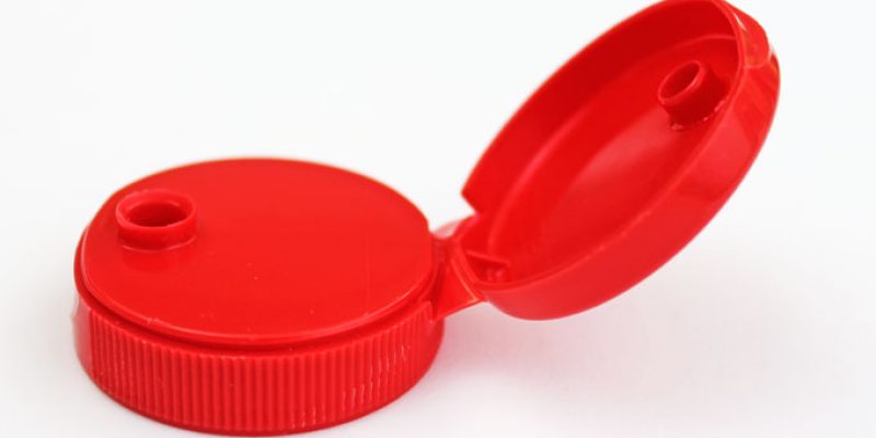
Select living hinges for high-volume consumer goods where unit cost is the primary driver. Examples include flip-top caps, disposable containers, and low-stress enclosure lids.
Choose mechanical hinges for applications involving heavy loads or wide opening angles. Industrial enclosures and automotive doors require the structural robustness that metal pivots provide.
- High Volume: Living hinges excel in runs exceeding 100,000 units.
- Heavy Load: Mechanical hinges support weights >5 kg easily.
Hybrid approaches can mitigate weaknesses by combining living hinges with rigid structural supports. This strategy allows for flexible movement while maintaining overall part rigidity.
Conduct a lifecycle cost analysis to determine the most economical solution. Consider initial tooling costs against long-term maintenance and assembly expenses.
| Criterion | Living Hinge | Mechanical Hinge |
|---|---|---|
| Initial Tooling | High (complex mold) | Low (standard parts) |
| Unit Cost | Very Low | Moderate to High |
| Maintenance | None (sealed) | Periodic lubrication |
Prototyping Strategies for Living Hinge Validation
3D Printing Techniques for Functional Testing
Selective Laser Sintering (SLS) is the preferred additive manufacturing method for initial hinge validation. It utilizes flexible nylon powders, such as PA12, to produce isotropic parts with consistent mechanical properties.
Fused Deposition Modeling (FDM) presents significant challenges due to layer adhesion weaknesses. The Z-axis orientation creates natural fracture points that fail under repeated bending stress.
Stereolithography (SLA) offers an alternative using specialized elastic resins for bend testing. However, these photopolymers often exhibit different creep behaviors compared to semi-crystalline polypropylene.
| Technique | Material Type | Primary Limitation | Best Use Case |
|---|---|---|---|
| SLS | Nylon (PA12) | Surface roughness | Kinematic validation |
| FDM | TPU/PLA | Layer delamination | Rough form fit checks |
| SLA | Elastic Resin | Brittle fatigue failure | Complex geometry verification |
Engineers should prioritize validating kinematics and range of motion in early prototypes. Fatigue life data from printed parts is rarely predictive of final injection-molded performance because 3D printing cannot replicate the specific molecular orientation achieved by injecting melt through a thin hinge section.
Urethane Casting for Near-Production Simulation
Silicone molds are created from high-fidelity master patterns to replicate production geometry. This process allows for the accurate simulation of gate locations and wall thicknesses.
Selecting the correct urethane compound is critical for mimicking polypropylene behavior. Shore hardness values between 80A and 95A typically approximate the flexibility of standard living hinges.
This method bridges the gap between rapid prototyping and expensive soft tooling. It provides a cost-effective solution for low-volume testing runs of 20–50 units.
- Mold Life: Silicone molds typically degrade after 25–50 casts.
- Cycle Time: Curing times range from 30 to 60 minutes per part.
- Accuracy: Dimensional tolerance is generally within ±0.15 mm.
Urethane casting enables realistic assembly testing without the lead time of steel tooling. It reveals interference issues that rigid 3D prints might mask.
Transitioning from Prototype to Mass Production
Prototype testing frequently exposes design flaws such as stress concentrations at sharp corners. Engineers must adjust radii to distribute bending stress evenly across the hinge thickness and eliminate notch effects.
Draft angles require refinement based on physical demolding experiences during casting. Insufficient draft leads to part distortion or mold damage in high-volume injection molding.
CAD data must be updated to reflect these geometric changes before tooling fabrication. Proper preparation reduces the need for costly mold modifications later in the process.
Pilot runs serve as the final validation step before full-scale manufacturing. These runs use actual production materials and processes to verify cycle times and part quality. Crucially, pilot runs validate that the melt flow direction passes through the hinge, ensuring proper molecular orientation.
| Parameter | Prototype Target | Production Target |
|---|---|---|
| Hinge Thickness | 0.5 – 0.7 mm | 0.25 – 0.5 mm |
| Bend Radius | > 0.5 mm | < 0.25 mm |
| Material | Simulant (Urethane/Nylon) | Polypropylene (PP) |
Successful transition relies on iterative feedback between testing results and tooling design. This approach minimizes risk and ensures robust hinge performance in the final product.
Enhancing Fatigue Life Through Molecular Orientation and Post-Molding Processes
The Science of Molecular Orientation in Polypropylene
Polymer chains align parallel to the flow direction during high-shear injection molding. This alignment creates anisotropic mechanical properties essential for hinge durability. In living hinges, it is critical that this flow direction is perpendicular to the hinge axis (through the hinge thickness).
Shear stress near the mold walls induces significant molecular orientation. This oriented layer acts as a reinforcing skin that resists crack propagation.
Rapid cooling locks these oriented chains in place before they can relax. Controlled cooling rates ensure a balance between surface crystallinity and core flexibility.
Amorphous regions provide the necessary free volume for chain movement. These areas allow the hinge to bend without immediate structural failure.
| Structural Region | Function in Hinge | Key Characteristic |
|---|---|---|
| Oriented Skin | Crack Resistance | High tensile strength |
| Amorphous Core | Flexibility | Low modulus, high elongation |
| Crystalline Lamellae | Stiffness | Thermal stability |
Cold Drawing and Annealing Techniques
Cold drawing mechanically stretches the hinge immediately after ejection. This process further aligns polymer chains beyond what molding achieves alone.
The procedure involves pulling the hinge to 10-20% strain at room temperature. This controlled deformation increases tensile strength in the flex direction.
Annealing heats the part to just below its melting point (typically 100-120°C for PP). This step relieves residual internal stresses caused by rapid cooling.
Stress relief prevents premature cracking during initial use cycles. It stabilizes the crystalline structure for consistent long-term performance.
Post-processing can increase cycle life from 10,000 to over 1,000,000 cycles. Quantifiable improvements depend on the degree of initial orientation.
| Process Step | Temperature/Condition | Primary Benefit |
|---|---|---|
| Cold Drawing | Ambient (20-25°C) | Increased chain alignment |
| Annealing | 100-120°C | Stress relief |
| Cooling | Controlled rate | Dimensional stability |
Optimizing Molding Parameters for Strength
High injection speeds generate the shear stress needed for molecular orientation. Typical speeds range from 80-120 mm/s for thin hinge sections.
Excessive pressure can cause flash, while insufficient pressure leads to short shots. Balance is critical for maintaining hinge geometry.
Mold temperatures must remain above 40°C to prevent premature freezing. Higher mold temps (60-80°C) promote better crystallization but extend cycle time.
Uniform cooling prevents warpage that could misalign the hinge axis. Warped hinges experience uneven stress distribution during flexing.
Packing pressure should be low to avoid over-packing the gate area. Over-packing restricts the natural shrinkage needed for proper orientation.
Hold time must be sufficient to gate freeze but not so long as to induce stress. Typical hold times are 2-5 seconds depending on wall thickness.
| Parameter | Recommended Range | Impact on Hinge |
|---|---|---|
| Injection Speed | 80-120 mm/s | Enhances orientation |
| Mold Temp | 40-80°C | Controls crystallinity |
| Packing Pressure | Low/Moderate | Prevents voids/stress |
| Hold Time | 2-5 s | Ensures gate freeze |
Quality control requires visual inspection for flow lines and whitening. Whitening indicates excessive stress or micro-void formation.
Regular fatigue testing validates process consistency across production batches. Sample parts should undergo accelerated life testing at defined frequencies.
Alternative Hinge Mechanisms for Structurally Demanding Applications
Introduction to Molded-In Knuckle Hinges
Molded-in knuckle hinges utilize interlocking cylindrical geometries to distribute stress evenly across the joint. This design prevents localized stress concentration, which is common in living hinges under high loads.
Pin selection significantly impacts durability and assembly efficiency. Metal pins offer superior shear strength, while molded plastic pins reduce part count and eliminate secondary assembly steps.
| Pin Type | Shear Strength | Assembly Complexity | Cost Impact |
|---|---|---|---|
| Metal (Steel/Brass) | High | Moderate (Insertion required) | Higher |
| Molded Plastic | Low to Medium | Low (Single-shot molding) | Lower |
Tooling for these hinges requires precise core alignment to maintain consistent knuckle clearance. Typical clearance gaps range from 0.1 mm to 0.25 mm to prevent binding during rotation.
Other Robust Hinge Alternatives
Snap-fit provide a cost-effective solution for temporary enclosures or low-cycle applications. These mechanisms rely on elastic deformation, limiting their use to materials with high fatigue resistance like Polypropylene. Note that for snap-fits, especially those with short beams (length-to-thickness ratio < 10:1), standard cantilever formulas often underestimate strain because they assume rigid walls. Designers should apply deflection amplification factors to account for wall deformation.
Film hinges utilize reduced wall thicknesses, often below 0.5 mm, to create flexible joints in lightweight packaging. This approach minimizes material usage but sacrifices structural rigidity and load-bearing capacity.
Integrated pivot points with bearing surfaces reduce friction without external lubricants. Designers often incorporate spherical or cylindrical bearing lands to manage radial and axial loads effectively.
- Snap-fit: Best for <100 cycles; requires high-elongation polymers.
- Film Hinge: Ideal for thin-walled containers; limited torque tolerance.
- Bearing Pivot: Suitable for continuous rotation; requires precise tolerances.
Multi-part assembly hinges allow for modular designs where different materials optimize specific functions. This method increases assembly time but enables complex geometries impossible with single-shot molding.
Selecting the Right Mechanism for Your Application
Engineers must first quantify static and dynamic loads to determine the required hinge geometry. Torque requirements dictate the knuckle diameter and pin material selection to prevent premature failure.
Environmental factors such as UV exposure, chemical contact, and temperature fluctuations affect material integrity. For outdoor applications, select UV-stabilized resins or stainless steel pins to mitigate degradation risks.
Manufacturing constraints often drive the final decision between integrated and multi-part solutions. Single-shot molding reduces labor costs but increases initial tooling complexity and expense.
| Criterion | Molded Knuckle | Snap-Fit | Multi-Part Assembly |
|---|---|---|---|
| Load Capacity | High | Low | Variable |
| Tooling Cost | High | Low | Medium |
| Assembly Time | Low | Low | High |
| Durability | Excellent | Fair | Good |
Case studies demonstrate that automotive glove boxes benefit from molded knuckles due to high cycle counts. Conversely, consumer electronics often use snap-fits for battery compartments to facilitate user serviceability.