
Two-Shot Molding vs. Overmolding: Choosing the Right Process for Your Needs
Core Definitions and Fundamental Differences
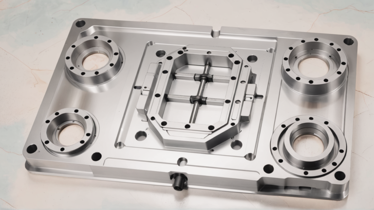
Two-shot molding, also known as 2K molding, injects two different materials in a single machine cycle. This process uses rotary or stack molds to ensure precise alignment without manual handling.
Overmolding involves molding a second material over a pre-formed substrate. This often requires moving parts between machines or using insert molding techniques.
- Cycle Efficiency: Two-shot molding is faster for high volumes due to automation.
- Alignment: Two-shot offers tighter tolerances, typically within ±0.05 mm.
- Use Case: Choose Two-shot for high-volume needs. Choose Overmolding for complex geometries or lower volumes.
Production Volume and Budget Considerations
Initial tooling costs differ significantly between the two methods. Two-shot molds are complex and expensive, often costing 30-50% more than standard tools.
Overmolding tools are simpler and cheaper to fabricate. However, per-unit labor costs are higher due to manual part transfer.
Lead times for two-shot tooling are longer due to complexity. Overmolding allows for faster project kickoff and easier scalability adjustments.
Suitability Assessment Framework
Select the right process by evaluating part geometry and bond requirements. Two-shot molding excels when strict aesthetic standards and seamless bonds are critical.
Overmolding is suitable when substrates are heat-sensitive or sourced externally. It accommodates materials with incompatible processing temperatures.
- Bond Strength: Two-shot provides superior chemical bonding due to simultaneous cooling.
- Complexity: Use Overmolding for undercuts that prevent ejection in a single mold.
- Example: Toothbrush handles often use Two-shot for grip integration. Medical device housings may use Overmolding for sterile component assembly.
The Two-Shot Injection Molding Process: Machinery and Cycle Sequence
Essential Machinery and Equipment Requirements
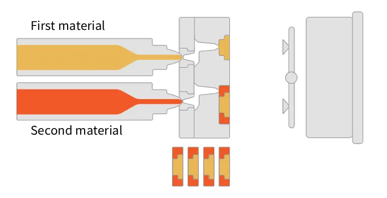
Two-shot injection molding requires specialized machines with two independent injection units. These units process different materials simultaneously or sequentially within a single cycle.
Rotary table systems are the most common mechanism for transferring parts between cavities.
- Horizontal Rotation: The mold rotates 180 degrees on a horizontal axis. This is standard for most general applications.
- Vertical Rotation: The mold rotates on a vertical axis. This design saves floor space and suits smaller components.
Stack mold systems offer high productivity by doubling cavity counts without increasing clamp force. Indexing plates provide an alternative to rotary tables for linear movement. They are ideal for rectangular parts where rotation is impractical.
Machine specifications must match the combined requirements of both shots.
Step-by-Step Cycle Sequence Breakdown
The cycle begins with injecting the first material, known as the substrate, into the initial cavity. This forms the structural core of the final part.
The substrate undergoes partial cooling to solidify its shape. It must remain hot enough to bond with the second material but firm enough to retain geometry.
The mold then rotates or indexes to transfer the substrate to the second cavity. Precision alignment is critical during this transfer to prevent flash.
The second injection unit melts and injects the overmold material onto the substrate. Chemical or mechanical bonding occurs at the interface during this step.
Final cooling solidifies the complete assembly before ejection. The finished part is removed, and the cycle repeats.
Optimizing timing is essential for production efficiency.
- Cooling Time: Dictated by the thickest wall section of either material.
- Rotation Speed: Must be fast enough to minimize idle time but slow enough to ensure stability.
- Injection Rate: Adjusted to prevent material degradation or excessive shear heat.
Automation and Quality Control Integration
Robotic arms handle part removal and transfer between mold stages. This automation ensures consistent cycle times and reduces labor costs.
In-process sensors monitor critical parameters in real time.
- Temperature Sensors: Track melt and mold temperatures to prevent thermal degradation.
- Pressure Transducers: Ensure consistent packing pressure for uniform part density.
Vision systems inspect parts immediately after ejection. They detect defects such as flash, short shots, or misalignment.
Precise mold alignment is vital for repeatability. Even minor deviations can cause bonding failures or dimensional errors. Regular maintenance of guide pins and bushings ensures long-term accuracy.
Material Compatibility and Bonding in Two-Shot Molding
Principles of Chemical and Mechanical Bonding
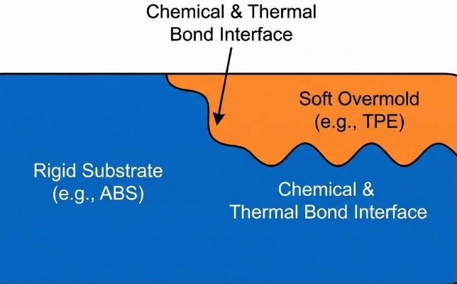
Chemical bonding occurs when polymer chains from two different shots intermingle at the molecular level. This requires materials with similar chemical structures or solubility parameters to fuse effectively.
Mechanical bonding relies on physical interlocking rather than molecular fusion. Designers create undercuts, holes, or textured surfaces to lock the second shot into the first substrate.
- Temperature: The substrate surface must remain above its glass transition temperature ($T_g$) during the second shot.
- Pressure: Adequate injection pressure ensures the molten material fills micro-textures for mechanical grip.
- Surface Energy: High surface energy promotes better wetting and adhesion between layers.
Delamination often results from contaminated surfaces or excessive cooling between shots. Cleaning molds regularly and minimizing cycle time gaps mitigates these risks.
Selecting Compatible Material Pairs
Choosing materials from the same polymer family significantly increases bond strength. For example, bonding a polypropylene (PP) substrate with a PP-based thermoplastic elastomer (TPE) yields reliable adhesion.
Common compatible pairs include TPE or TPU over rigid plastics like ABS, PC, or PP. These combinations balance flexibility with structural integrity without requiring adhesives.
Incompatible pairs, such as silicone over PP, require mechanical locks for retention. Tie layers or primers can bridge chemically distinct materials but add process complexity.
Always review Material Data Sheets (MDS) for specific adhesion ratings. Look for data on peel strength and compatibility charts provided by resin manufacturers.
Testing and Validation of Material Bonds
Peel tests measure the force required to separate the two material layers. Shear strength measurements assess resistance to sliding forces parallel to the bond interface.
Environmental factors like humidity and temperature fluctuations can weaken bonds over time. Conduct aging tests to simulate long-term exposure to heat, UV light, or chemicals.
- Humidity: Test at 85% relative humidity to check for hydrolysis risks.
- Temperature: Cycle between -40°C and 85°C to identify thermal stress failures.
Prototyping with actual production tools validates material choices before full-scale runs. This step identifies processing windows and prevents costly mold reworks later.
Key Design Considerations for Two-Shot Molded Parts
Wall Thickness Transitions and Geometry
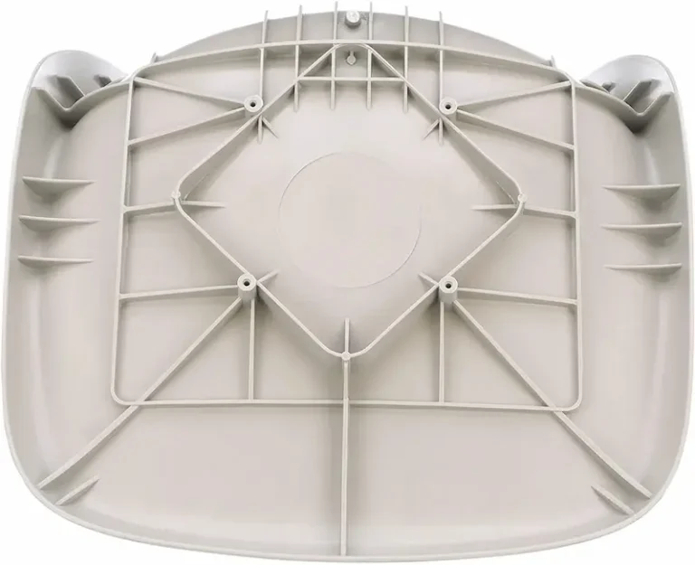
Uniform wall thickness is critical to prevent sink marks and warpage. Aim for consistent thickness across both the substrate and overmold, typically between 1.5 mm and 3.0 mm.
- Use gradual transitions with a maximum ratio of 3:1 when changing wall thickness.
- Avoid sharp internal corners by adding radii equal to at least 0.5 times the wall thickness.
Rib design must balance structural integrity with material flow. Keep rib thickness at 50-60% of the adjacent wall thickness to prevent sinking.
- Ensure rib height does not exceed three times the rib base width.
- Add small fillets at the rib base to reduce stress concentration.
Draft Angles and Ejection Requirements
Draft angles facilitate part ejection and prevent damage to the mold. Standard recommendations vary based on surface finish and material type.
Ejection strategies must account for the softness of the overmold material. Pin placement should avoid high-stress areas to prevent deformation.
- Use stripper plates for large, thin-walled parts to distribute ejection force evenly.
- Ensure adequate draft on the second shot cavity to prevent part sticking during ejection.
Gate Placement and Flow Dynamics
Strategic gate location ensures complete filling of both shots without defects. Place gates in thick sections to promote proper packing and minimize visible marks.
- Balance flow lengths to ensure uniform pressure distribution across the part.
- Position gates away from aesthetic surfaces to hide witness lines.
Venting is essential to release trapped air and prevent burn marks. Include vents with a depth of 0.01-0.03 mm at the end of fill paths.
- For multi-cavity molds, maintain symmetry to ensure balanced filling.
- Use family molds only if flow lengths are nearly identical to avoid uneven packing.
Surface Finish and Aesthetic Design
Managing parting lines and witness lines is crucial for visual appeal. Align parting lines with natural edges or features to hide seams.
- Ensure texture compatibility between substrate and overmold to avoid mismatched finishes.
- Use color contrast strategically to highlight functional areas or branding.
Ergonomic grips benefit from soft-touch overmolds with specific Shore hardness values. Typical overmold hardness ranges from Shore A 40 to Shore A 70 for comfortable handling.
- Design grip patterns with sufficient depth (0.5-1.0 mm) for tactile feedback.
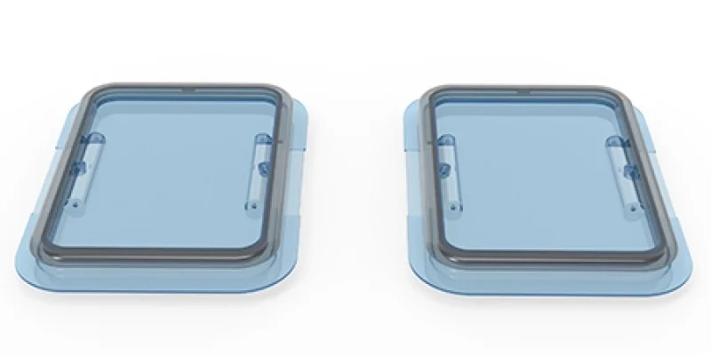
- Verify transparency effects by testing material compatibility for clear-on-clear applications.
Cost-Benefit Analysis: Justifying the Investment in Two-Shot Molding
Initial Tooling Investment Breakdown
Two-shot molds require high-grade hardened steel, such as H13 or S7, to withstand repeated thermal cycling. The complex geometry of rotating cores or sliding plates increases machining time and cost by 30% to 50% compared to single-shot tools.
- Complexity: Multi-axis movements require precise engineering tolerances within ±0.02mm.
- Cavity Count: Higher cavity counts exponentially increase initial capital expenditure.
Amortize these higher upfront costs over larger production runs to reduce per-unit expense. Regular maintenance schedules prevent costly downtime and extend tool life beyond 1 million cycles.
Operational Cost Savings and Efficiency Gains
Eliminating secondary assembly steps removes the need for adhesives, fasteners, or ultrasonic welding. This integration reduces direct labor costs by up to 40% per unit produced.
Integrated manufacturing minimizes handling errors that typically cause scrap in multi-step processes. Consistent mold alignment ensures part accuracy, lowering rejection rates to below 2%.
Consolidating multiple components into a single SKU simplifies inventory management. Warehousing costs drop significantly as you store fewer distinct parts and sub-assemblies.
Long-Term ROI and Strategic Advantages
Calculate the break-even point by dividing the additional tooling cost by the per-unit savings from assembly elimination. High-volume production runs, typically exceeding 100,000 units, justify the initial investment quickly.
- Quality: Mechanical bonding ensures consistent alignment without human error.
- Value: Premium soft-touch overlays allow for higher market pricing.
Sustainability metrics improve due to reduced energy consumption from eliminated assembly lines. Less material waste occurs because there are no excess adhesives or separate packaging for small components.
Automotive console cases often show a 15% ROI improvement within the first year. Consumer electronics housings benefit from tighter seals and enhanced durability, reducing warranty claims.