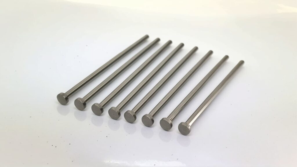
Ejector pins are critical components in the injection molding process used to eject finished parts from the mold cavity once the plastic has solidified. These pins are typically cylindrical rods made of hardened steel that push the molded part from the core side of the mold.
The ejection process begins after the mold cools and the part solidifies. Ejector pins are activated by a plate mechanism, pushing the part out without damaging its surface or structure. According to a study by the Society of Plastics Engineers, improper ejection accounts for nearly 20% of surface defects in molded products, highlighting the importance of precise pin operation.
Ejector pins not only ensure the complete removal of parts but also contribute to mold efficiency. A properly placed and functioning ejector system reduces cycle time and prevents part distortion, which is essential for maintaining production quality and consistency.
There are several types of ejector pins available, each suited to specific applications:
- Standard Ejector Pins: These are the most commonly used and are suitable for general-purpose applications.
- Hardened Ejector Pins: Designed for high-wear environments, especially when molding abrasive materials like glass-filled plastics.
- Shoulder and Blade Pins: Used for parts with complex geometries or thin walls, offering precision in ejection without damaging the part.
Each type has its own benefits. For instance, hardened pins offer longer tool life, while blade pins provide better ejection for flat or thin parts. The selection depends largely on the molded part’s geometry, material, and expected production volume. Industry guidelines suggest selecting pins that can withstand the expected ejection force without flexing or breaking, which ensures reproducibility and longevity of the mold.
Choosing the correct ejector pin involves several considerations:
- Material Compatibility: Pins must be made of materials that resist wear and corrosion. For example, nitrided steel is commonly used for its hardness and longevity.
- Pin Size and Placement: The diameter, length, and location of ejector pins must match the part design to prevent warping or incomplete ejection. Research from MoldMaking Technology indicates that improperly sized or placed pins can increase part rejection rates by up to 15%.
-
Design Integration: The pin must be integrated in a way that maintains part aesthetics and structural integrity. I think there are 3 key considerations for ejector pin location:
- Prioritize placement near areas with smaller draft angles, since these are more prone to sticking.
- Position pins in structurally strong areas, such as at rib intersections, to avoid stress marks.
- Use pins in locations where air entrapment might occur to assist in venting and ensure smooth ejection.
Finally, sourcing high-quality pins from reputable suppliers is crucial. Manufacturers like DME and Hasco offer standardized pins that meet global quality norms, ensuring consistent performance across production runs.
Effective ejector pin design plays a critical role in minimizing part defects during the injection molding process. Guidelines recommend that ejector pins be designed to apply uniform ejection force, reducing the risk of part warping or cracking. For example, industry standards suggest using flat or slightly domed pin ends to distribute force evenly, especially on complex geometries.
Best practices for pin placement include avoiding thin or fragile areas and instead targeting robust sections of the part. Studies indicate that placing pins at the junctions of ribs or bosses—where material strength is higher—leads to a 30% reduction in ejection-induced damage (Plastics Technology, 2020). In line with my opinion, I recommend prioritizing pin locations near areas with smaller draft angles. These areas are more prone to sticking, so well-positioned pins help reduce ejection force and minimize part distortion.
To ensure proper ejection, techniques such as using guided ejector systems and synchronizing ejection timing are employed. These methods ensure that force is applied uniformly and that parts are removed without bending or surface deformation.
Several variables influence where ejector pins should be placed, including the part’s geometry, resin type, and wall thickness. For instance, materials with low shrinkage rates (e.g., ABS) behave differently during cooling than high-shrinkage materials (e.g., polypropylene), which may require additional or repositioned pins to prevent sticking.
Surface texture also plays a role. Glossy finishes are more likely to show ejector pin marks, so pins should be placed in hidden or low-visibility areas when possible. According to a study by MoldMaking Technology (2019), improper pin placement on visible Class A surfaces led to a 40% increase in rejected parts due to cosmetic flaws.
From a design perspective, mold flow and cooling must be considered. Uneven cooling can cause differential shrinkage, leading to part sticking in certain areas. Finite Element Analysis (FEA) tools are often used to simulate mold filling and cooling behaviors, helping designers identify potential sticking points. In my opinion, pins should also be placed near regions prone to air entrapment, such as deep ribs or corners. These areas are natural candidates for pin placement since they also help vent trapped gases, reducing burn marks.
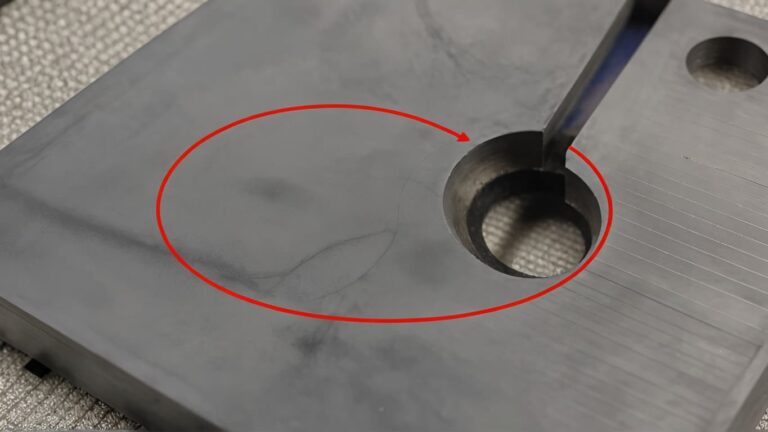
Cosmetic issues such as pin push marks, white spots, or sink marks can significantly impact product appearance and customer satisfaction. These defects are often caused by excessive ejection force, improper pin sizing, or poor alignment. In consumer electronics, for example, even minor blemishes on housing components can lead to part rejection, emphasizing the importance of defect-free surfaces.
To avoid visible marks, engineers often recess the pin slightly or use textured pin heads that match the surface finish. Techniques such as using sleeve ejectors or lifters for complex geometries can also help. A 2021 survey by the Society of Plastics Engineers found that using non-traditional ejector systems reduced visible marks by up to 60% in high-precision parts.
Testing and validation during mold trials are essential. Engineers use inspection tools like coordinate measuring machines (CMMs) and high-resolution imaging to detect early signs of pin-related flaws. Adjustments—such as modifying pin diameter or location—can then be made accordingly. My view is that strategic placement, especially at rib junctions or near small draft angles, helps reduce both functional and cosmetic issues during ejection.
Ejector pins play a critical role in the overall efficiency of the injection molding process. They are responsible for removing the molded part from the cavity without causing damage or deformation, which directly affects part quality and production speed. According to a study published in the Journal of Manufacturing Processes (2019), improper ejector pin placement can increase cycle time by up to 20% due to incomplete ejection or part warping.
To optimize ejector pin usage, several strategies can be implemented:
-
Strategic Placement: I think there are 3 considerations for ejector pin location:
- Prioritize positions with smaller draft angles to assist in smooth ejection.
- Place pins in structurally strong areas such as rib junctions to avoid deformation.
- Target areas prone to air entrapment to aid in venting and reduce defects. These principles are widely supported in mold design handbooks, such as the SPI Mold Standards.
-
Simulation Tools: Using mold flow analysis software can help predict the best ejector pin positions, reducing trial-and-error during mold development. Autodesk Moldflow, for instance, has shown to reduce development time by 15–30%.
-
Design for Manufacture (DFM): Early collaboration between designers and mold engineers ensures that ejector pin requirements are integrated during product design, minimizing redesigns.
Proper use of ejector pins can also significantly reduce cycle time. For example, research conducted by the Society of Plastics Engineers (SPE) indicates that optimizing ejection systems can cut ejection time by up to 40%, thus increasing hourly output.
Common issues with ejector pins include pin galling, breakage, and misalignment. These problems often arise from excessive friction, poor lubrication, or incorrect pin material. In high-volume production environments, even minor pin failures can halt operations and cause costly downtime.
To address these issues, manufacturers can:
- Use Proper Lubrication: Apply high-temperature lubricants to reduce wear and prevent sticking.
- Select Appropriate Materials: Hardened tool steels like H13 are preferred for their wear resistance.
- Monitor Pin Alignment: Regular inspection can detect early signs of misalignment, which can be corrected before causing damage.
Maintenance is crucial to ensure long-term functionality. A preventive maintenance schedule that includes cleaning, inspection, and replacement of worn pins can extend mold life significantly. According to a report by Plastics Technology, molds with regular ejector pin maintenance showed 50% fewer downtime incidents.
Recent advancements in ejector pin technology have brought significant improvements to injection molding performance. New materials such as DLC-coated (Diamond-Like Carbon) pins offer superior wear resistance and lower friction, resulting in longer service life. Research from the Fraunhofer Institute found that DLC-coated pins lasted up to 5 times longer than traditional uncoated pins in high-cycle applications.
High-performance pins also contribute to better part quality and reduced maintenance needs. For example:
- Self-lubricating Pins: Eliminate the need for external lubricants, reducing contamination risks.
- Vented Ejector Pins: Help release trapped air, minimizing burn marks and voids.
- Temperature-Controlled Pins: Improve part cooling and reduce cycle time.
Looking forward, the trend is toward smart ejector systems equipped with sensors to monitor pin movement and detect anomalies in real time. These systems can alert operators to potential issues before they cause defects or downtime, aligning with Industry 4.0 objectives for intelligent manufacturing.
The global market offers a wide variety of ejector pins tailored to meet the demands of precision molding. Leading suppliers such as MISUMI, DME, and Hasco provide standardized ejector pins in various materials including hardened tool steel, HSS, and stainless steel. These products are often categorized by shape (straight, stepped, shoulder), length, and diameter.
Key features to consider include:
- Hardness: Typically between HRC 45 and HRC 60.
- Surface finish: Polished or coated for wear resistance.
- Tolerance: High precision, often ±0.005 mm.
When evaluating ejector pins, engineers should consider:
- Application-specific needs: For example, use nitrided pins for high-wear environments.
- Compatibility with mold design: Ensure alignment with cavity and core dimensions.
- Supplier reliability: ISO-certified manufacturers are preferred for consistent quality.
A 2021 report by Grand View Research estimates the precision mold component market will grow at a CAGR of 4.8% through 2028, driven by demand in automotive and electronics sectors—underscoring the importance of selecting high-quality ejector pins.
Custom ejector pin orders start with a clear specification of design needs. Here’s a typical process:
- Initial Inquiry: Contact the manufacturer with application details.
- Technical Drawing Submission: Include 2D/3D CAD files with dimensions, tolerances, and material requirements.
- Quote and Lead Time: Manufacturer provides cost and delivery estimate.
- Prototype (if needed): For critical components, a prototype may be produced for testing.
- Final Production and Delivery.
To facilitate this process efficiently, provide:
- Mold layout and cavity details.
- Material selection (e.g., SKD61, H13).
- Operating temperature and cycle count expectations.
Using custom-designed ejector pins offers several benefits:
- Improved part ejection: Reduces stress on molded parts.
- Enhanced mold longevity: Better fit and alignment reduce wear.
- Optimized cycle times: Precision fit accelerates production.
I think there are 3 considerations for ejector pin location:
- Close to areas with smaller draft angles: These zones are harder to eject, and pin assistance minimizes part deformation.
- Structural support locations: Such as at the junction of ribs, which can handle ejection force better.
- Air entrapment zones: Ejector pins can also vent trapped air, reducing defects like burn marks.
According to a study published in the “International Journal of Advanced Manufacturing Technology” (2019), strategic pin placement reduced ejection force by 15%, improving surface quality and reducing cycle time.
Common specifications for ejector pins include:
- Diameter: Ranges from 0.5 mm to 20 mm.
- Length: Custom or standard lengths, usually up to 300 mm.
- Material: SKD61 (chrome molybdenum steel), H13, or stainless steel.
- Hardness: Typically HRC 45–60, depending on heat treatment.
Interpreting these specs is essential:
- Diameter tolerance affects fit in guide holes.
- Length must match mold depth and ejection stroke.
- Material selection determines wear resistance and thermal expansion behavior.
Matching specifications to your project ensures:
- Reliable performance: Reduces risk of pin breakage or sticking.
- Cost efficiency: Avoids over-specification and unnecessary expense.
- Compliance: Meets quality standards like ISO 9001 or DIN 1530.
Understanding ejector pin specs helps engineers align component design with end-use requirements, critical for achieving high mold productivity and part quality.
When looking to buy high-quality ejector pins, it’s crucial to choose from reputable suppliers with a proven track record in mold component manufacturing. Renowned manufacturers such as DME, MISUMI, and Progressive Components are widely recognized for consistent quality and global distribution. These companies often provide comprehensive catalogs with customization options, certifications, and CAD data for engineering integration.
To evaluate the quality and reliability of ejector pin vendors, consider the following:
- Material certifications and tolerance specs
- Customer reviews and ISO compliance
-
Availability of technical support and documentation
According to a 2022 survey by Plastics Technology, 78% of mold engineers prioritize vendors that can provide material traceability and dimensional inspection reports.
For sourcing ejector pins both online and offline, use platforms like Thomasnet, Alibaba (for bulk orders), or local distributors for urgent needs. Online sourcing offers broader selection and convenience, but offline purchasing can provide faster fulfillment and better after-sales service.
The ordering process for ejector pins typically involves selecting the pin type (straight, stepped, shoulder, etc.), specifying dimensions, material, and quantity. Most vendors offer online configuration tools, allowing engineers to input exact tolerances. A request for quote (RFQ) is then submitted, followed by supplier confirmation and payment.
Delivery policies vary widely:
- Standard delivery: 3–7 business days
- Expedited shipping: Available for a premium
-
Global shipping: Offered by large suppliers like DME and MISUMI
MISUMI, for instance, provides guaranteed lead times and same-day shipping for standardized items, which is critical for minimizing downtime in tool shops.
Creating an account with major suppliers usually involves providing company details, tax ID, and payment preferences. Once registered, users can track orders, reorder parts, and access invoice history. Some platforms, like Progressive Components, offer order management tools and real-time inventory updates, streamlining procurement workflows.
Common materials used for ejector pins include:
- SKD61 (H13 equivalent): High wear resistance and heat resistance
- 420 Stainless Steel: Corrosion resistance, suitable for medical or food-grade molds
-
M2 Tool Steel: High hardness, used in high-wear environments
According to data from MoldMaking Technology, 420 stainless steel is preferred in 40% of medical mold applications due to its corrosion resistance.
Comparing material properties:
| Material | Hardness (HRC) | Corrosion Resistance | Heat Resistance | Typical Use Cases |
|---|---|---|---|---|
| SKD61 | 48–52 | Moderate | High | General-purpose molds |
| 420 Stainless | 48–50 | High | Moderate | Food & medical molds |
| M2 Tool Steel | 60–65 | Low | High | Abrasive environments |
When selecting the right material, consider usage conditions such as cycle time, mold temperature, and exposure to corrosive agents. My opinion is that ejector pin location also plays a role in material choice. For example, areas near small draft angles or potential air entrapment zones may require pins with higher durability or corrosion resistance to withstand operational stress and chemical exposure.
Ultimately, understanding the interplay between application demands and material properties helps extend tool life and reduce maintenance costs.


