
Understanding the Importance of Draft Angles
Why Draft Angles Are Critical for Manufacturing Success
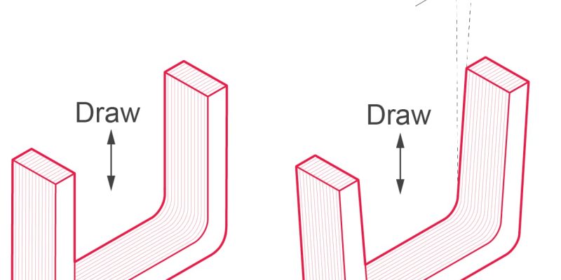
Draft angles are essential for preventing part damage during ejection. Without sufficient taper, rigid plastics can crack or warp under ejection pin pressure.
Insufficient draft often leads to vacuum lock and ejection failures because air cannot enter the gap between the part and the core quickly enough. Surface scratches and drag marks are common consequences of zero-draft designs, requiring secondary finishing operations that increase costs.
How Draft Facilitates Part Release
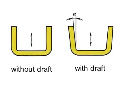
Friction reduction is the primary mechanical function of a draft angle. Plastic materials shrink as they cool from melt temperature to ambient conditions, creating high normal forces against the mold steel. The tapered surface allows vertical movement with less resistance.
- Shrinkage Rate: Typical thermoplastics shrink 0.5% to 2.0%.
Most molded parts, excluding lenses or mirror finishes, require some texture. Nearly perfect smooth surfaces (mirrors) can be costly and often do not provide the correct aesthetics or ergonomics. Parts may require deep textures for better grip or to hide typical wear and tear. The deeper the required texture, the greater the required draft angle. A good design rule of thumb is that for every $0.025 \mathrm{~mm}$ of texture depth, $1^{\circ} \sim 1.5^{\circ}$ of draft angle is needed.
Standard Recommended Draft Angles by Surface and Geometry
Guidelines Based on Surface Finishing
The relationship between draft angle and surface area contact is linear but critical. A small increase in angle drastically reduces the effective contact length during ejection. Industry standards recommend minimum draft values based on surface finish.
| Surface Type | Recommended Minimum Draft | Reason |
|---|---|---|
| Polished (SPI A1) | 0.5° – 1.0° | Low friction allows minimal taper. |
| Fine Texture (VDI 24) | 1.5° – 2.0° | Texture peaks create mechanical locking. |
| Coarse Texture (VDI 34) | 3.0° – 5.0° | Deep grains require significant clearance. |
Textured surfaces require more draft than polished surfaces to prevent dragging.
For example, common MoldTech textures illustrate these requirements:
- MT-11010: Depth of $0.025\mathrm{mm}$, requires $1.5^{\circ}$ or greater draft angle.
- MT-11020: Depth of $0.038\mathrm{mm}$, requires $2.25^{\circ}$ or greater draft angle.
- MT-11030: Depth of $0.050\mathrm{mm}$, requires $3^{\circ}$ draft angle (mold manufacturers may require more).
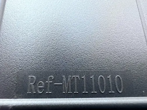
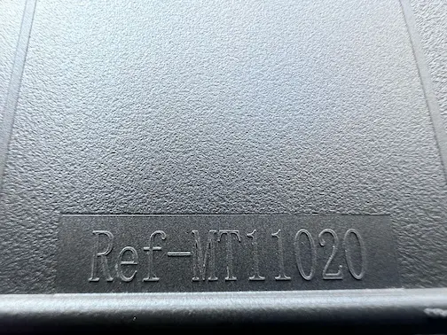
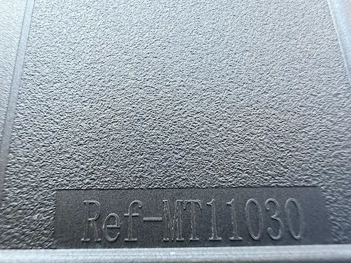
Some deeper pattern-style textures have depths up to $0.178 \mathrm{~mm}$, which requires a $10.5^{\circ}$ draft angle. This implies that if a cup design requires a $0.178 \mathrm{~mm}$ texture depth, it needs a $21^{\circ}$ opening angle to accommodate the texture on both sides.
Guidelines Based on Part Depth and Wall Thickness
Start with a baseline draft angle of 1 degree per side for general plastic parts. This standard applies to most uncomplicated geometries with moderate depth. Increase the draft angle as the part depth increases relative to its width.
| Feature Type | Minimum Draft Angle | Notes |
|---|---|---|
| General Walls | 1° | Standard starting point |
| Deep Draws (>50mm) | 2° – 3° | Prevents vacuum lock and scraping |
| Ribs (Internal) | 0.5° – 1° | Keep low to maintain structural integrity |
| Bosses (External) | 1° – 2° | Ensure smooth release from core pins |
Apply stricter minimums for ribs and bosses to balance strength and manufacturability. Internal ribs typically need at least 0.5 degrees, while external bosses benefit from 1 to 2 degrees.
Tall, thin-walled structures are prone to sticking and deformation, you can use higher draft angles, such as 2 degrees or more, to reduce friction forces during mold opening. Compensate for varying wall thicknesses by adjusting draft locally.
Calculating and Optimizing Draft for Specific Plastic Resins
Material-Specific Draft Recommendations for Common Resins
Crystalline polymers generally need more draft than amorphous ones. Their higher shrinkage rates create greater interference with mold steel, demanding steeper angles for reliable ejection.
| Material Type | Shrinkage Range | Recommended Draft |
|---|---|---|
| ABS | 0.4% – 0.7% | 1° |
| Nylon (PA) | 1.0% – 2.5% | 1.5° – 2° |
| Polycarbonate (PC) | 0.5% – 0.7% | 1° – 2° |
| Polypropylene (PP) | 1.0% – 2.5% | 1.5° – 2° |
Special Considerations for Engineering Plastics
Glass-filled Nylon and ABS require careful handling due to their stiffness. Use a minimum draft of 1.5° to overcome the higher ejection forces caused by glass fibers. Abrasive filled materials accelerate mold wear on vertical walls; specify hardened steel inserts for high-wear areas to maintain draft integrity over production runs.
| Resin Category | Key Challenge | Draft Recommendation |
|---|---|---|
| Glass-Filled | High Stiffness | Min 1.5° |
| PEEK | High Temp | Min 2.0° |
| Abrasive Fills | Mold Wear | Hardened Steel + 1.5° |
High-temperature resins like PEEK have low thermal expansion but high modulus. They grip the core tightly as they cool, requiring draft angles of at least 2.0° for deep cores. Balance structural needs with ejection requirements by avoiding zero-draft cosmetic surfaces. Slight tapers improve cycle time and reduce the risk of part damage during ejection.
Impact of Draft Angles on Fit, Function, and Assembly
Ensuring Proper Fit for Mating Parts and Enclosures
Draft angles directly influence the dimensional accuracy of mating components. Even small tapers can cause significant gaps or interference when parts stack up.
- Tolerance Stack-up Management: A 1-degree draft on a 50mm wall creates a 0.87mm variance in width. This variation must be accounted for in the overall assembly tolerance budget.
- Uniform Gap Control: Designers should specify maximum allowable taper to maintain consistent aesthetic gaps. Typical cosmetic gaps range from 0.2mm to 0.5mm depending on part size.
Snap-fits and clips require precise draft to function without breaking during ejection or assembly. Insufficient draft leads to high ejection forces and potential part damage.
| Feature Type | Recommended Draft | Reason |
|---|---|---|
| External Snap | 1° – 2° | Reduces ejection force |
| Internal Clip | 3° – 5° | Prevents undercuts |
| Mating Wall | 0.5° – 1° | Maintains fit precision |
Aligning draft directions is critical for multi-part assemblies. Misaligned tapers cause binding during final assembly steps.
- Ensure all mating surfaces pull in the same direction relative to the mold open axis.
- Verify that cumulative taper does not exceed the designed clearance between halves.
Functional Considerations for Buttons, Keys, and Interfaces
Moving parts like buttons and switches demand strict draft control to prevent binding. Excessive taper changes the effective diameter along the travel path.
- Binding Prevention: Keep draft below 0.5° for long-travel sliding mechanisms. Higher angles create uneven contact pressure against the housing.
- Actuation Consistency: Uniform wall thickness ensures consistent spring-back and feel. Variable draft leads to unpredictable actuation forces.
Guide pins and holes serve as alignment features during assembly. Incorrect draft here compromises the entire unit’s structural integrity.
- Use minimal draft (0.25° – 0.5°) on guide pins to maintain tight locational accuracy.
- Provide slightly larger clearance on mating holes to accommodate minor molding variations.
Waterproofing and sealing surfaces are highly sensitive to draft-induced geometry changes. A tapered surface prevents uniform compression of O-rings or gaskets.
- Avoid draft on critical sealing lands whenever possible.
- If draft is unavoidable, limit it to less than 0.5° and adjust groove dimensions accordingly.
- Test seal compression at both the top and bottom of the tapered interface.