Dimensional Guidelines for Injection Molding Boss Design
Wall Thickness and Height Ratios
Based on design and assembly experience, the outer diameter of a boss is typically recommended to be maintained within 2.0 to 2.4 times the outer diameter of the screw or insert. This ratio ensures appropriate connection strength and assembly stability.
To prevent sink marks on the opposite surface, the boss wall thickness should follow rib thickness guidelines, generally keeping the wall thickness (T) relative to the nominal wall thickness (t) within recommended limits to avoid excessive material accumulation.
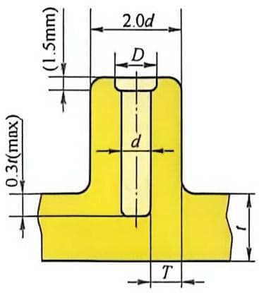
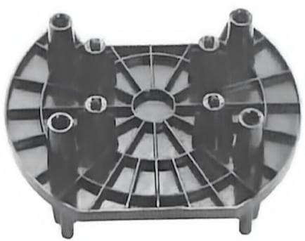
The height of the boss should be limited to prevent core pin deflection and cooling issues. It is recommended that the boss height be less than 3 times its outer diameter. High bosses with draft angles can lead to increased thickness at the bottom section, extended cycle times, and slower core cooling, which may affect hole dimensions.
Draft Angles and Surface Finish Requirements
Applying appropriate draft angles to the boss outer diameter facilitates easy part ejection. Without sufficient draft, parts are prone to scratching during ejection, and the mold may suffer wear, affecting both part surface quality and mold life.
To avoid these issues, it is recommended to apply a draft angle of $0.5^{\circ}$ or greater on the outer wall of the boss. To reduce the risk of damaging the part during ejection, the draft angle in the boss hole should be at least $0.25^{\circ}$.
| Surface Condition | Recommended Draft | Reason |
|---|---|---|
| Boss Outer Wall | $\ge 0.5^{\circ}$ | Prevents scratching and mold wear |
| Boss Inner Hole | $\ge 0.25^{\circ}$ | Reduces risk of part damage |
| Deep Boss (>3x Dia) | >1.5° | Reduces vacuum lock |
Hole Geometry and Core Pin Specifications
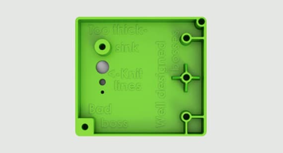
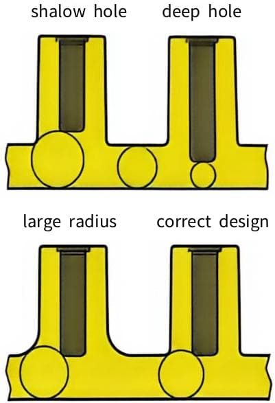
In part design, even if assembly does not require full depth, the boss hole should typically extend to a level flush with the base wall. Shallow holes can lead to increased local thickness, causing sink marks or voids.
Conversely, holes that are too deep can weaken the base wall thickness, leading to filling problems, weld lines, or surface defects. Therefore, design should ensure uniform thickness of the connecting walls.
Sink marks occur when the local wall thickness at the boss base creates excessive material accumulation. The radius at the base of the boss should be between 0.25 and 0.5 times the nominal wall thickness.
Preventing Cosmetic Defects in Boss Features
Mitigating Sink Marks at Boss Bases
Additionally, to lower the risk of stress concentration and fracture, the bottom of the boss should use a smooth radius transition rather than sharp edges. While larger radii minimize stress concentration, they also increase the likelihood of sink marks or voids.
Selecting smaller screws or inserts can effectively prevent bosses from becoming too thick. If the boss wall thickness exceeds the recommended ratio, consider adding grooves around the bottom of the boss to reduce material accumulation, thereby effectively alleviating and reducing sink mark issues.
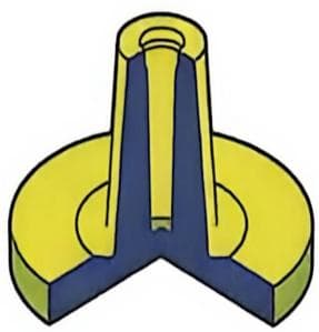
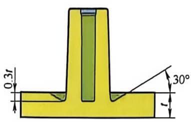
Advanced molding techniques can further reduce internal voids and surface depressions. Gas-assist injection molding introduces nitrogen pressure into the melt core.
| Technique | Application | Benefit |
|---|---|---|
| Vacuum Assist | Thick sections | Removes trapped air, improves packing |
| Gas-Assist | Long flow paths | Reduces sink by internal pressure |
| Bottom Grooves | Excessive Wall Thickness | Reduces material accumulation |
Optimize processing parameters to compensate for localized shrinkage. Increase packing pressure by 10–15% specifically for the boss gate region. Extend hold time until the gate freezes to prevent backflow.
Reducing Warpage and Distortion
Differential cooling rates between thick bosses and thin walls generate internal stresses. These stresses manifest as warpage once the part ejects from the mold.
It is recommended to ensure that the spacing between bosses is greater than or equal to 2 times the nominal wall thickness. This spacing helps prevent the formation of difficult-to-cool thin-wall regions and reduces the risk of warpage due to uneven cooling.
Symmetrical placement of bosses balances shrinkage forces across the part geometry. Asymmetrical designs often twist due to uneven contraction during solidification.
Managing Flow Lines and Vents
Flow lines converge around circular boss structures, creating visible weld lines. These defects weaken the structure and mar the cosmetic appearance.
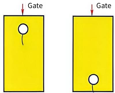
For bosses with weld lines, it is essential to pay attention to the impact of the weld line on performance. The gate position significantly affects the strength of the boss hole due to its influence on weld line formation. This difference must be fully considered during design.
- Gate Positioning: Place gates away from direct line-of-sight to boss bases.
- Distance Rule: Maintain a minimum distance of 3x the boss diameter from the gate.
Surface texture choices can mask minor flow imperfections around boss areas. A medium grit blast (e.g., VDI 24) diffuses light reflection effectively.
Avoid high-gloss finishes on parts with complex boss geometries. Textured surfaces reduce the visual contrast of weld lines by scattering light.
Structural Reinforcement Strategies for Standalone Bosses
Integrating Ribs for Enhanced Strength
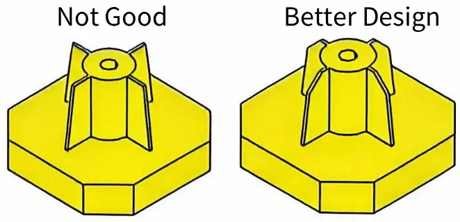
Ribs and gussets can provide stability to parts without increasing wall thickness, which is particularly beneficial for parts with thin walls that may be subject to stress. Note that the thickness of ribs and gussets should generally not exceed 60% of the nominal wall thickness. To avoid excessively thick sections where ribs and gussets intersect with walls, these features should be thinner than the main wall thickness.
Rib Count: Use three or four ribs arranged symmetrically around the boss.
The placement of gussets in a mold often interferes with proper direct venting, so it is advisable to avoid gusset designs that are likely to trap gas and lead to filling and packing problems. By modifying the geometry or thickness of the gussets, trapped air can be directed away from the gusset zone toward areas with better venting capability.
Troubleshooting Common Boss Design Failures
Addressing Core Pin Deflection and Breakage
Core pin deflection often manifests as inconsistent boss inner diameters or visible bending marks on the molded part. This typically occurs when the length-to-diameter ratio exceeds recommended limits without adequate support. It is recommended that boss height be less than 3 times its outer diameter to mitigate these risks.
- Root Cause Analysis: High injection pressures create lateral forces that exceed the pin’s yield strength.
- Visual Inspection: Check for elliptical boss holes rather than perfect circles to identify early bending.
Design modifications such as stepped pins or guided inserts significantly increase structural rigidity. These features reduce the unsupported length of the core pin during the injection phase. If the boss height exceeds 5 times the outer diameter, consider coring out from both sides or splitting the boss to reduce the effective pin length.
| Modification Type | Benefit | Application Constraint |
|---|---|---|
| Stepped Pins | Increases diameter at base | Requires larger mold base space |
| Guided Inserts | Prevents lateral shift | Adds complexity to mold maintenance |
| Pilot Holes | Reduces initial resistance | Requires secondary machining step |
Selecting high-wear steel alloys like H13 with proper heat treatment is critical for longevity. Hardness values between 48-52 HRC provide a balance between toughness and wear resistance.
Implementing pilot holes or pre-forms reduces the lateral load on the core pin during cavity filling. This approach minimizes the risk of sudden breakage in high-volume production runs.
Solving Ejection Difficulties and Sticking
Vacuum lock is a primary cause of sticking in deep, blind boss holes with tight tolerances. The rapid cooling of plastic creates a pressure differential that holds the part against the core. Applying appropriate draft angles is crucial; a draft of $0.5^{\circ}$ or more on the outer wall and at least $0.25^{\circ}$ in the hole is recommended to facilitate ejection.
- Diagnosis: Listen for a distinct “pop” sound during ejection, indicating vacuum release.
- Measurement: Verify if the boss depth exceeds five times its diameter, increasing vacuum risk.
Enhancing ejection efficiency requires specialized mechanisms such as sleeve ejectors or air poppets. Sleeve ejectors provide uniform force around the boss circumference, preventing deformation.
| Ejection Method | Force Distribution | Best Use Case |
|---|---|---|
| Sleeve Ejector | Uniform radial | Deep bosses with thin walls |
| Air Poppet | Internal pressure | Blind holes prone to vacuum |
| Stripper Plate | Broad surface area | Shallow bosses with large footprints |
Optimizing draft angles to at least 1-2 degrees per side reduces friction significantly. A mirror polish (SPI A-1) on the core pin further minimizes adhesion forces.
Troubleshooting sticking also involves reviewing packing pressure and cooling time settings. Excessive packing compresses the plastic against the pin, while premature cooling increases shrinkage grip.
Preventing Fastener Stripping and Assembly Issues
Boss walls must have sufficient thickness to resist hoop stress generated by self-tapping screws. Based on design and assembly experience, the outer diameter of the boss is typically recommended to be maintained within 2.0 to 2.4 times the outer diameter of the screw or insert. This ensures appropriate connection strength and assembly stability.
- Stress Concentration: Thin walls crack under radial expansion during screw insertion.
- Material Limits: Brittle plastics like polystyrene require thicker walls than flexible polypropylene.
Selecting appropriate materials or inserts is vital for applications requiring repeated assembly. Brass or stainless steel inserts provide superior thread durability compared to direct plastic threading.
| Fastening Method | Durability Cycle | Torque Resistance |
|---|---|---|
| Direct Threading | Low (1-5 cycles) | Moderate |
| Ultrasonic Insert | High (50+ cycles) | High |
| Press-fit Insert | Medium (10-20 cycles) | High |
Calculating torque limits requires analyzing the plastic’s tensile strength and the boss geometry. Over-torquing leads to immediate stripping or delayed stress cracking.
Using threaded inserts offers clear advantages for durability but increases unit cost and cycle time. Direct threading is cost-effective for single-use assemblies but risks failure under high load.