Hole Design
Core pins are raised features in the mold that form internal features such as holes, openings, and grooves. They can also be used to remove excess material from thick sections, helping maintain a uniform wall thickness.
Whenever possible, holes should be designed so that the core pin can be removed directly in the mold opening direction. Otherwise, side actions or hydraulic core pulls may be required, increasing mold complexity, cost, and maintenance.
Hole location and size should be carefully designed to simplify mold construction and minimize any reduction in part strength. Through holes are generally easier to mold than blind holes because the core pin is supported at both ends.
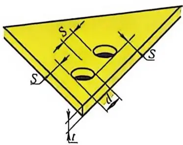
As shown in Figure 4-39, the minimum distance S between two holes, or between a hole and another feature, should be at least equal to the hole diameter d. The surrounding wall should also be as thick as practical to reduce the risk of cracking.
Threaded holes require additional attention because the threaded area can create internal stresses that make the plastic more brittle. As a general guideline, the distance from a hole to the edge of the part should be 2–3 times the hole diameter.
Selecting a Proper Depth-to-Diameter Ratio
Blind holes are formed by core pins supported from only one side of the mold, as shown in Figure 4-40.
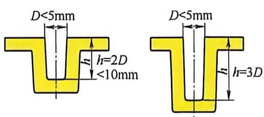
As the hole becomes deeper, the unsupported core pin is subjected to significant lateral forces during mold filling. These forces can deflect the core pin, causing dimensional errors. In severe cases, repeated bending may lead to fatigue failure of the mold steel.
As a general rule, the depth of a blind hole should not exceed 3 times its diameter (3:1). For holes smaller than 5 mm in diameter, the recommended ratio should be reduced to 2:1.
If the plastic fills symmetrically around the core pin or the core is located in a low-flow area, the depth-to-diameter ratio may be increased to 5:1.
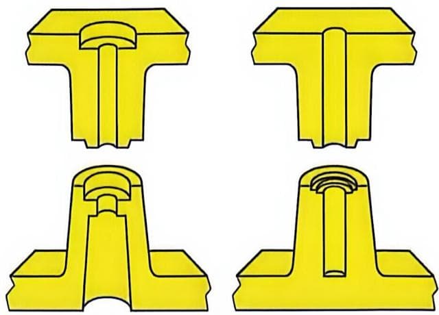
Whenever possible, avoid long unsupported core pins by redesigning the part. For example, a deep hole can often be divided into two shorter holes, as shown in Figure 4-41.
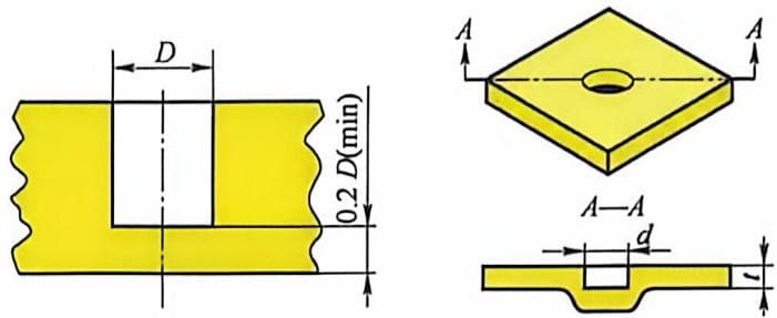
For blind holes, the material thickness beneath the hole should be at least 20% of the hole diameter to prevent sink marks or surface defects on the opposite side, as shown in Figure 4-42. A better design maintains a uniform wall thickness and avoids sharp corners that may create stress concentrations.
Through Hole Design
For through holes (Figure 4-43), the core pin is supported from both sides of the mold, allowing much greater rigidity.
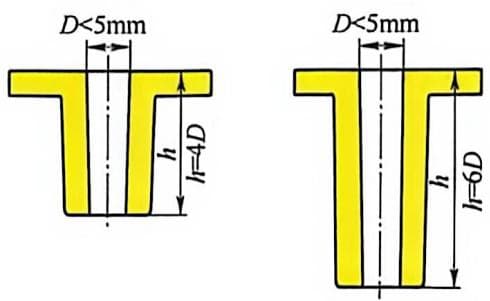
Another common method is to use two separate core pins fixed to each mold half. When the mold closes, the two pins align and lock together.
Compared with blind holes, the allowable core length for a through hole is typically twice as long. For even longer core pins, the mold must be carefully designed to ensure balanced filling pressure and minimize core deflection during injection.
Interlocking Core Design
When a core pin is supported at both ends, the recommended depth-to-diameter ratio can generally be increased to 6:1. If the plastic fills symmetrically around the core pin, the ratio may reach 10:1.
The effectiveness of the support depends on how the core ends are connected. As shown in Figure 4-44, an interlocking core provides much better resistance to deflection than a simple end-to-end contact.
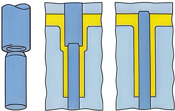
For through holes formed by a single core pin, the opposite mold half can include an interlocking feature to provide additional support.
Preventing Core Misalignment
Core misalignment can reduce the effective hole diameter when the hole is formed by matching core pins.
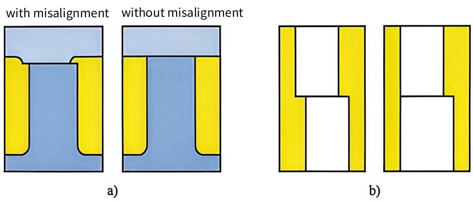
Whenever possible, locate the entire hole in one mold half (Figure 4-45a). Another option is to use a slightly larger core pin (Figure 4-45b) so that minor misalignment does not reduce the required hole size.
For holes with tight tolerances that cannot be stepped, interlocking features may be added to the core pins to correct slight misalignment. Although effective, these features increase mold manufacturing and maintenance costs.
For short through holes that can be molded with a single core pin, simply adding a radius to one side of the hole eliminates the need for matching core pins and avoids misalignment, similar to the design shown in Figure 4-44.