How High-Frequency Vibrations Create Molecular Bonds
Ultrasonic welding is one of the most widely used methods for joining thermoplastics. It utilizes high-frequency (20–40 kHz) ultrasonic energy to generate low-amplitude (1–25 μm) mechanical vibrations. A piezoelectric transducer expands and contracts rapidly to drive the sonotrode (horn), converting electrical energy into these mechanical oscillations.
When thermoplastic materials are subjected to ultrasonic vibration, sinusoidal standing waves are generated within the material. Part of the energy is dissipated through intermolecular friction, causing significant internal heat accumulation; another part is transmitted to the welding interface, where boundary friction causes localized heating. This heat melts the polymer chains specifically at the joint line without affecting the bulk material.
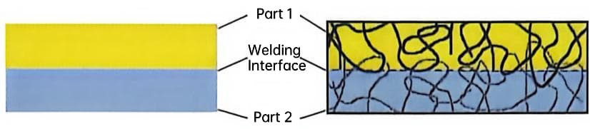
The optimal transmission of ultrasonic energy to the joint and the subsequent melting behavior depend on both the geometry of the weldment and the ultrasonic absorption characteristics of the material.
Key Physics Concepts Influencing Weld Quality
Weld energy is a function of amplitude, frequency, and time. Higher amplitudes (e.g., 20–60 microns) deliver more energy per cycle to the joint interface.
| Parameter | Typical Range | Impact on Weld |
|---|---|---|
| Frequency | 20 kHz / 40 kHz | Determines penetration depth and part size suitability |
| Amplitude | 1–25 µm | Controls heat generation rate and melt volume |
| Weld Time | 0.1–1.0 s | Dictates total energy input and joint depth |
Acoustic impedance mismatches can reflect energy away from the weld zone. Materials with similar impedances transmit vibrational energy more efficiently.
Inconsistent trigger force leads to variable start times for melting. This variability directly impacts joint consistency and repeatability in high-volume production.
A common misconception is that external heaters melt the plastic. In reality, the heat is generated internally via intermolecular friction and viscoelastic hysteresis, as well as boundary friction at the interface.
Strong Joints Design Guidelines for Ultrasonic Welding
Mastering Joint Geometries: Energy Directors vs. Shear Joints
In ultrasonic welding, joint configurations vary widely and can be primarily divided into two categories. The first category, which includes the most common joint types like butt joints and step joints, utilizes ultrasonic vibration perpendicular to the surfaces to be connected. The second category involves vibration parallel to the mating surfaces, creating a shearing action that completes the weld; various shear joints and miter joints belong to this category.
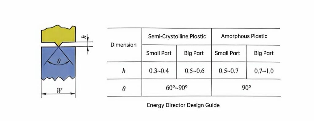
The Energy Director (ED) is a standard geometry for the first category, suitable for semi-crystalline and amorphous thermoplastics. It features a triangular profile with a tip angle between 30° and 90°. A typical ED height ranges from 0.25 mm to 0.5 mm. This small contact area concentrates vibrational energy to initiate rapid melting at the interface.
Shear joints are particularly suitable for welding semi-crystalline materials with sharp and narrow melting points. For these materials, traditional energy directors are not ideal because the material may degrade or recrystallize before it can flow smoothly across the welding interface to form an effective weld.
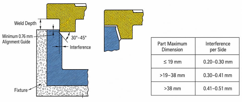
During the welding process, the small initial contact area of the shear joint melts first. As the parts fit together in a manner similar to a grinding action, the melting process continues along the vertical wall. This effectively eliminates contact with air, preventing premature solidification. In this way, a strong and airtight seal can be obtained. To ensure the smooth progress of the welding process, rigid side wall support is required to prevent part deformation. The top of the joint should be designed as shallow as possible, similar to a lid shape, while maintaining sufficient structural integrity to withstand potential internal deformation. Shear joints provide part alignment and uniform contact area.
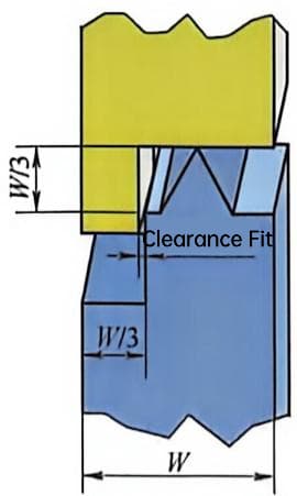
For large weldments or weldments with deep and soft tops, shear joints are designed as shown in below.
When flash is unacceptable, a “trap” can be incorporated into the shear joint design.
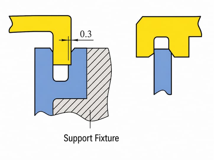
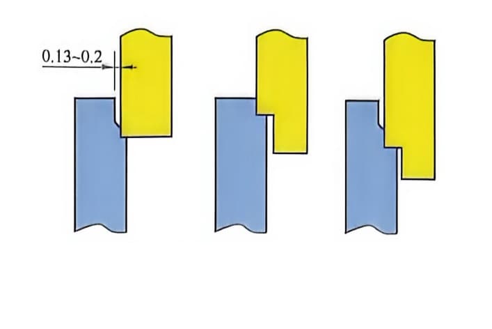
Shear joints are suitable for cylindrical parts but perform poorly for rectangular parts, as the walls of rectangular parts tend to vibrate perpendicular to the welding axis. They are also not suitable for flat circular parts subjected to annular stress. In parts with square corners or rectangular designs, using shear joints can produce airtight seals and high weld strength, but significant visible flash will appear on the upper surface after welding.
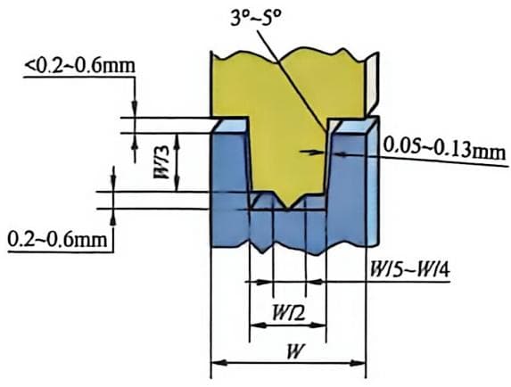
Tongue-and-groove designs provide superior lateral alignment during the welding process. They restrict part movement while allowing vertical collapse of the joint interface.
- Energy Director: Best for general assembly, fast cycle times, and non-hermetic applications.
- Shear Joint: Essential for pressure vessels, medical devices, and crystalline polymers.
- Tongue-and-Groove: Used when tight positional tolerance is critical before energy application.
Critical Design Parameters for Optimal Energy Transfer
To ensure the best welding effect, the welding interface should be located on a single plane parallel to the contact surface of the ultrasonic horn. In this way, ultrasonic energy can propagate evenly to every point in the weld, producing a uniform welding effect. At the same time, the part surface in contact with the horn should also remain parallel to the welding interface to ensure the efficiency of energy transmission. Several joint designs unfavorable for welding are shown as below and should be avoided to improve welding quality.
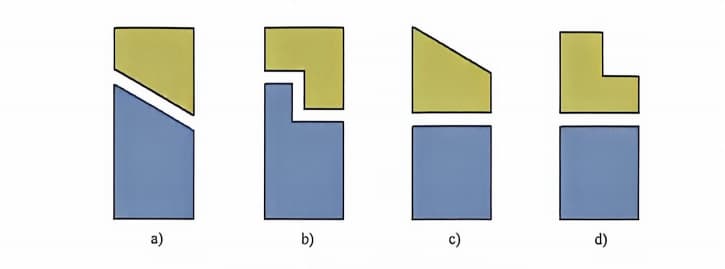
Wall thickness ratios significantly impact energy transmission and weld quality. The nominal wall thickness should generally remain consistent near the joint interface. Avoid sudden changes in cross-section that cause stress concentrations or uneven heating. A gradual transition radius of at least 0.5 mm helps distribute ultrasonic vibrations evenly.
Standoff heights control the initial gap between mating parts before welding begins. Typical standoff values range from 0.2 mm to 0.5 mm depending on material hardness. This gap prevents premature contact and allows the horn to reach full amplitude before engagement. Proper standoffs also accommodate minor variations in part molding dimensions.
Uniform energy distribution requires careful attention to part geometry and horn design. Large parts may need multiple weld points or stepped horns to maintain consistent pressure.
- Contact Area: Keep the initial contact area small to maximize energy density.
- Corner Radii: Use fillets instead of sharp corners to reduce stress risers.
- Flash Traps: Incorporate overflow channels to capture excess molten material.
Incorporating Fixturing and Support into Part Design
Rigid support directly beneath the weld zone is non-negotiable for effective energy transfer. Any flexibility in the fixture absorbs vibrational energy instead of transmitting it to the joint. Use steel or aluminum fixtures with precise machining to match the part contour. This minimizes energy loss and ensures consistent weld depth across production runs.
Part features must accommodate nesting fixtures to prevent lateral movement during welding. Include locating pins or datum surfaces that align the part securely within the tooling. Deflection during horn descent can lead to weak joints or part damage. Design ribs or gussets near the weld area to increase local stiffness without adding excessive mass.
Tolerance considerations are vital for maintaining consistent gap control and weld quality. Mating parts should have tight tolerances on the weld interface dimensions.
- Fixture Material: Hardened steel for high-volume production; aluminum for prototyping.
- Support Proximity: Support must be within 6 mm of the weld interface.
- Gap Control: Maintain a uniform gap of ±0.1 mm across the entire joint line.
Material Compatibility: Selecting Plastics for Ultrasonic Welding
Amorphous vs. Semi-Crystalline Thermoplastics
Amorphous thermoplastics like ABS, PC, and PS possess a random molecular structure. This allows them to soften gradually over a broad temperature range during ultrasonic vibration. Semi-crystalline materials such as PP, PE, and Nylon have ordered molecular regions. They transition abruptly from solid to melt, requiring higher energy input and precise control to prevent premature resolidification.
- Energy Absorption: Amorphous plastics transmit ultrasonic energy efficiently with minimal damping.
- Heat Generation: Semi-crystalline plastics absorb more energy at the interface but lose heat rapidly to the surrounding mass.
Welding dissimilar amorphous materials is feasible if their chemical structures are compatible. Solvent compatibility often indicates successful weldability between different amorphous resins.
Key Material Properties Affecting Weldability
Melt Flow Index (MFI) significantly influences joint integrity and aesthetic quality. Low MFI resins (<10 g/10 min) generally produce stronger welds with reduced flash formation. High MFI materials flow too easily under pressure. This often results in excessive flash and weak interfacial bonding due to material expulsion from the joint area.
Additives and fillers alter acoustic transmission and energy absorption rates. Glass-filled resins dampen ultrasonic waves, requiring higher amplitude settings to achieve adequate melt. Moisture content must be strictly controlled for hygroscopic materials like Nylon and PET. Water vaporizes during welding, creating voids that reduce tensile strength by up to 50%.
| Material Factor | Impact on Welding | Recommended Action |
|---|---|---|
| Glass Fillers (>15%) | High energy damping | Increase amplitude or use energy directors |
| Hygroscopic Resins (e.g., Nylon) | Voids and weak bonds | Pre-dry to <0.2% moisture content |
| High Stiffness | Efficient energy transmission | Optimize horn contact area |
Testing and Validating Material Choices
Peel tests and tensile strength assessments quantify bond reliability across different resin grades. Target tensile strengths should exceed 80% of the base material’s yield strength for structural applications. Identifying incompatible combinations prevents costly production failures. Dissimilar semi-crystalline plastics rarely form coherent bonds due to mismatched melting points and crystallization rates.
Table 6-5 shows the compatibility of thermoplastics for ultrasonic welding. Please note that changes in resin composition may lead to slight differences in ultrasonic welding results, and compatibility only indicates that materials can be compatible under certain specific conditions. Therefore, it is recommended to conduct sufficient testing and verification in practical applications.
Table 6-5 Compatibility of Thermoplastics for Ultrasonic Welding
| Material Code | Abbreviation | Fully Compatible | Partially Compatible |
|---|---|---|---|
| ABS | A | A, B, D | T |
| ABS/PC | B | A, B, K | D |
| POM | C | C | — |
| PMMA | D | A, D, B, E, J, K | T |
| Copolymer PMMA | E | E, A, D, Q | T |
| CA | F | F | — |
| Fluoroplastics | G | G | — |
| PA | H | H | — |
| PPO | I | I, Q, D, K | T |
| PAI | J | J | — |
| PC | K | B, K, D, I | R |
| PET | L | L | — |
| PE | M | M | — |
| PMP | N | N | — |
| PP | O | O | — |
| PP | P | P | — |
| PS | Q | I, Q, E | T |
| PSU | R | R | K |
| PVC | S | S | — |
| SAN | T | A, D, E, I | Q |
- Automotive Case Study: PP bumper fascias use matching homopolymer grades to ensure consistent weld depth.
- Medical Case Study: PC housings utilize amorphous compatibility for hermetic seals without particulate generation.
Source weldable grades directly from major resin manufacturers’ technical data sheets. Look for specific “ultrasonic weldable” designations or recommended MFI ranges for processing stability.
System Anatomy: Key Components of an Ultrasonic Welder
The Generator: Powering the Process
The generator converts standard line voltage (e.g., 120/240 VAC) into high-frequency electrical energy, typically at 20 kHz or 40 kHz. This precise conversion drives the piezoelectric elements within the transducer stack. Modern digital generators offer superior control compared to older analog systems. They provide real-time feedback on power, amplitude, and frequency stability.
- Automatic Frequency Tracking: Adjusts output to match the resonant frequency of the tooling stack during operation.
- Energy Monitoring: Tracks joules delivered to ensure consistent weld quality across cycles.
Safety features include overload protection and thermal monitoring to prevent component damage. These systems adhere to industrial standards like ISO 9001 for process reliability.
The Converter Stack: Transducers and Boosters
Piezoelectric ceramics in the transducer expand and contract when exposed to high-frequency electrical signals. This action converts electrical energy into mechanical vibrations at ultrasonic frequencies. The booster modifies the amplitude of these vibrations before they reach the horn. It acts as a mechanical transformer to increase or decrease displacement.
| Component | Primary Function | Typical Material |
|---|---|---|
| Transducer | Electrical to mechanical conversion | Piezoelectric Ceramic |
| Booster | Amplitude amplification/attenuation | Titanium Alloy |
Transducers often use titanium housings for their high strength-to-weight ratio and acoustic efficiency. Proper cooling is essential to prevent depolarization of the ceramic elements. Regular inspection of bolt torque and surface cleanliness extends transducer lifespan. Loose connections can cause arcing and catastrophic failure of the stack.
The Tooling: Horns (Sonotrodes) and Anvils
Ultrasonic horns must be tuned to resonate at the system’s operating frequency, typically within ±50 Hz. Material selection balances acoustic transmission with wear resistance.
- Titanium: Preferred for high-amplitude applications due to low internal damping.
- Aluminum: Used for prototyping or low-wear scenarios but degrades faster.
Horn faces are machined to match part geometry, ensuring uniform energy distribution. Poor contact leads to inconsistent welds and potential part marking. The anvil supports the bottom part and absorbs residual vibration energy. It must be rigid enough to prevent energy loss into the machine frame. Monitor tooling for pitting, cracking, or changes in resonance frequency. Replace horns when amplitude delivery drops below 90% of original specifications.
Strategic Assembly: Comparing Ultrasonic Welding to Other Methods
Ultrasonic Welding vs. Adhesive Bonding
Ultrasonic welding offers significant speed advantages by eliminating cure times. Cycle times typically range from 0.1 to 1.0 seconds, whereas adhesives often require minutes or hours to set. This rapid processing enables high-volume throughput without bottlenecking production lines. The process removes the need for consumables like glues, solvents, and primers. This elimination reduces material costs and avoids Volatile Organic Compounds (VOCs) in the workspace. Manufacturing facilities benefit from cleaner air quality and simplified regulatory compliance.
Consistency is inherently higher with automated ultrasonic systems compared to manual adhesive application. Human error in bead placement or volume control is completely removed from the equation. Energy input is precisely monitored to ensure uniform weld strength across every unit. Adhesives remain superior for specific niche applications involving dissimilar materials. They are often necessary when bonding plastics to metals, glass, or ceramics where fusion is impossible. Large surface area bonds also favor adhesives due to the limited contact area of ultrasonic horns.
Ultrasonic Welding vs. Mechanical Fasteners and Vibration Welding
Eliminating screws, clips, and rivets reduces Bill of Materials (BOM) costs significantly. Secondary assembly steps such as torqueing or snapping are removed from the workflow. This streamlining lowers labor requirements and minimizes potential points of mechanical failure. Aesthetic integrity is preserved since no visible fastener heads mar the product surface. The weld line is often subtle or can be hidden within the part geometry. This is critical for consumer electronics and medical devices requiring smooth, clean exteriors.
Vibration welding suits larger parts but requires heavier, more expensive equipment. Ultrasonic systems generally have lower initial tooling costs for small to medium components. However, vibration welding may provide deeper weld penetration for thick-walled crystalline plastics. Environmental impact is minimized through reduced waste generation. There are no leftover screws, plastic clips, or chemical containers to dispose of. The energy-efficient nature of ultrasonic generators further lowers the carbon footprint per assembled unit.
| Feature | Ultrasonic Welding | Mechanical Fasteners | Vibration Welding |
|---|---|---|---|
| Cycle Time | < 1 second | 5–30 seconds | 2–10 seconds |
| Consumables | None | Screws, clips | None |
| Part Size | Small to Medium | Any | Medium to Large |
| Aesthetics | Clean, no marks | Visible heads | Witness marks possible |
Limitations and When to Choose Alternative Methods
Part geometry strictly limits ultrasonic welding effectiveness. The technique requires rigid structures to transmit high-frequency vibrations efficiently. Flexible or overly large parts dampen energy before it reaches the joint interface. Soft materials like low-density polyethylene (LDPE) present coupling challenges. These resins absorb vibrational energy rather than transmitting it to the weld zone. Engineers often switch to hot plate welding or spin welding for such flexible polymers.
Initial capital investment for ultrasonic generators and custom horns can be high. However, operational savings from speed and lack of consumables offset this over time. Break-even points are typically reached faster in high-volume production runs exceeding 50,000 units annually. Selecting the optimal method requires balancing volume, material, and design constraints. Low-volume projects may favor adhesives due to lower tooling costs. High-volume plastic assemblies benefit most from the speed and repeatability of ultrasonic technology.
| Decision Factor | Prefer Ultrasonic | Prefer Alternative |
|---|---|---|
| Annual Volume | > 50,000 units | < 10,000 units |
| Material Type | Rigid Thermoplastics | Elastomers / Metals |
| Joint Geometry | Simple, flat interfaces | Complex, 3D contours |
| Budget Focus | Low operational cost | Low upfront tooling cost |