
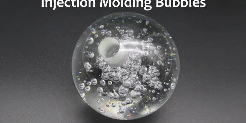
Diagnosing the Root Causes of Injection Molding Bubbles and Defects
Understanding the Mechanics of Air Entrapment and Gas Formation
Air entrapment occurs when the melt front advances faster than the air can escape through vents. High injection speeds trap pockets of air, creating localized pressure spikes up to 200 MPa.
- Shear Heat Generation: Excessive screw rotation speeds generate frictional heat. This can degrade resin if barrel temperatures exceed material-specific limits (e.g., >280°C for PC).
- Gas Sources: Decomposing polymers release volatile gases. These gases form internal bubbles distinct from surface defects.
| Defect Type | Visual Characteristic | Primary Cause |
|---|---|---|
| Surface Blister | Raised, shiny bump | Trapped air near mold wall |
| Internal Void | Sunken or hollow center | Vacuum pull during cooling |
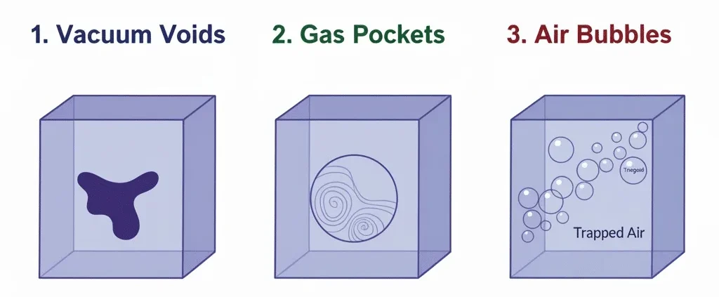
Differentiating Between Common Bubble-Like Defects
Trapped air bubbles are typically spherical and located at the end of fill. Moisture-induced splay appears as silver streaks radiating from the gate.
- Diesel Effect: Compressed air ignites due to adiabatic heating. This causes black burn marks at the venting areas.
- Location Analysis: Defects near the gate suggest moisture or shear degradation. Defects at the far end indicate poor venting or slow filling.
Cavitation erosion creates rough, pitted surfaces on the steel, not just plastic defects. Standard gas pockets leave smooth internal walls within the plastic part.
The Role of Material Properties in Bubble Formation
Recycled materials often contain higher volatile content than virgin resin. Pre-drying is critical; aim for moisture levels below 0.02% for hygroscopic polymers like Nylon 6.
- Additive Impact: Flame retardants decompose at lower temperatures. This releases gases that form micro-voids if back pressure is insufficient.
- Viscosity Effects: Colorant carriers can alter melt viscosity. Higher viscosity traps gases more easily, requiring adjusted processing parameters.
| Polymer Type | Gas Permeability | Drying Requirement |
|---|---|---|
| Polyethylene (PE) | Low | Minimal |
| Polycarbonate (PC) | Moderate | Strict (4 hrs @ 120°C) |
| Nylon 6 (PA6) | High | Critical (4-6 hrs @ 80°C) |
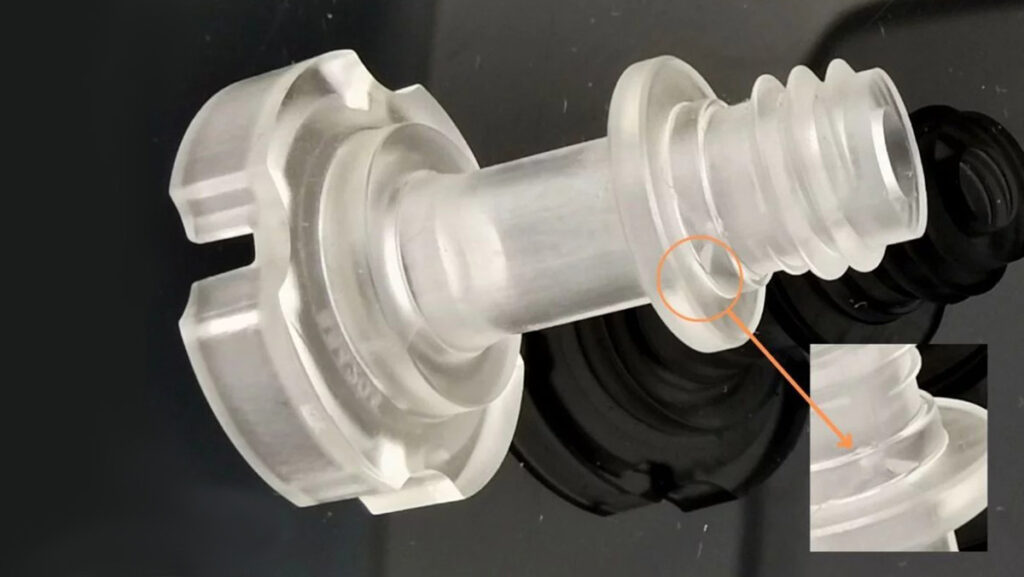
Practical Troubleshooting Steps and Parameter Adjustments
Optimizing Injection Speed and Pressure Profiles
Use multi-stage injection to stabilize the melt front. Start with a slow fill (10-20% speed) to vent air, then ramp up for the bulk fill.
| Stage | Speed Setting | Purpose |
|---|---|---|
| Initial | Low (10-20%) | Allows air escape through vents |
| Middle | High (60-80%) | Fills cavity before freezing |
| Final | Low (10-15%) | Prevents flash and gas trapping |
Adjust hold pressure to compensate for shrinkage without trapping gas. Excessive hold pressure can force gas into the part surface, causing burns.
Fine-tune back pressure to ensure proper melt homogenization. A range of 5-15 bar is typically sufficient for most commodity resins.
Temperature Control Strategies for Gas Reduction
Lower barrel temperatures to prevent resin degradation and gassing. Degradation releases volatile gases that cause splay marks.
- Rear Zone: Set slightly above melting point to feed solid pellets.
- Middle/Front Zones: Optimize for shear heating rather than external heat.
Optimize mold temperature to control skin formation and gas venting. Higher mold temps (e.g., 80°C for PC) improve gas diffusion but increase cycle time.
Monitor shear heat generation through screw rotation speed adjustments. High RPM generates excessive internal heat, leading to localized degradation.
Screw Recovery and Back Pressure Adjustments
Set appropriate back pressure to compress the melt and remove air. This forces trapped air out through the feed throat during recovery.
- Too Low: Melt contains voids and inconsistent density.
- Too High: Excessive shear heat and longer recovery times.
Ensure sufficient cushion size to maintain consistent packing pressure. A cushion of 3-5 mm prevents the screw from bottoming out.
Troubleshoot screw slippage that introduces air into the melt stream. Slippage occurs when the check ring fails or back pressure is too low. Verify check ring integrity if cushion values fluctuate by more than ±1 mm.
Best Practices in Mold Design to Prevent Air Entrapment
Designing Effective Venting Systems
Proper vent dimensions are critical for allowing air to escape without leaking molten plastic. Use a depth of 0.01–0.03 mm for standard resins like PP or ABS. High-viscosity materials such as PC may require depths up to 0.05 mm to prevent flash.
| Resin Type | Typical Vent Depth (mm) | Recommended Width (mm) |
|---|---|---|
| Polypropylene (PP) | 0.01 – 0.02 | 5 – 10 |
| Polycarbonate (PC) | 0.03 – 0.05 | 5 – 10 |
| Nylon (PA66) | 0.01 – 0.02 | 5 – 10 |
Place vents at the end of fill paths and where weld lines form. Porous steel inserts help vent trapped air in deep ribs or blind holes. Schedule regular cleaning every 5,000–10,000 shots to remove carbon buildup.
Gate Placement and Runner System Optimization
Position gates to ensure smooth, laminar flow rather than turbulent injection. Fan gates or film gates spread the melt front to reduce jetting risks. This approach minimizes air pockets caused by high-velocity streams hitting mold walls.
Balance runner systems to ensure simultaneous filling of all cavities. Avoid sharp corners and sudden thickness changes in the flow path. These features create dead zones where air gets trapped and cannot escape.
Advanced Mold Features for Gas Management
Vacuum venting systems remove air before injection for high-precision parts. This method is essential for optical lenses or medical components with strict tolerance limits. It reduces burn marks and short shots caused by compressed air pockets.
Use overflow wells to capture cold slugs and initial trapped air. Ensure draft angles exceed 1° to prevent vacuum lock during ejection. Strategic texturing can hide minor surface blemishes from residual gas traces.
Material Drying and Handling for Hygroscopic Resins
The Science of Moisture-Induced Bubbling
Hygroscopic polymers like Nylon, PET, and PC undergo hydrolysis when exposed to heat and moisture. This chemical reaction breaks polymer chains, reducing molecular weight and weakening mechanical strength.
- Steam Formation: Trapped water vaporizes at molding temperatures (200°C–300°C), creating micro-voids.
- Visual Defects: These voids manifest as “silver streaks” or splay on the part surface.
| Resin Type | Critical Moisture Limit | Primary Risk |
|---|---|---|
| Nylon 6/6 | < 0.1% | Hydrolysis & Voids |
| PET | < 0.02% | Molecular Degradation |
| Polycarbonate | < 0.02% | Surface Splay |
Proper Drying Procedures and Equipment Setup
Desiccant dryers are essential for hygroscopic resins, maintaining air dew points between -40°C and -60°C. Standard hot air ovens cannot achieve these low humidity levels required for effective drying.
- Temperature Control: Dry Nylon at 80°C–90°C and PC at 120°C to avoid clumping or degradation.
- Residence Time: Calculate time based on hopper capacity; typical ranges are 2–4 hours.
Verify dryness using Karl Fischer titration for lab accuracy or infrared analyzers for quick checks. Never rely solely on timer settings without periodic moisture validation.

Best Practices for Material Handling and Storage
Prevent re-absorption by minimizing exposure time during transfer from the dryer to the molding machine. Use closed-loop conveying systems with dry air purges to maintain a consistent environment.
- Storage: Seal opened bags immediately and store in a low-humidity room (<50% RH).
- Regrind Management: Limit regrind usage to <25% to prevent inconsistent moisture uptake.
Unprotected material can absorb critical moisture levels within minutes in humid conditions. Always keep hopper lids closed and inspect seals regularly for air leaks.
Distinguishing Trapped Air Bubbles from Vacuum Voids
Visual and Structural Differences Between Defect Types
Vacuum voids typically form in the core of thick-walled sections, far from the gate locations. These defects exhibit smooth, shiny interiors caused by the material pulling away from itself during cooling.
In contrast, trapped air bubbles often have rough, oxidized surfaces and appear near the end of fill or weld lines. Understanding this surface texture difference is critical for accurate root cause analysis.
| Feature | Vacuum Void (Shrinkage) | Trapped Air Bubble |
|---|---|---|
| Location | Part core, thick sections | End of fill, weld lines |
| Surface Texture | Smooth, shiny | Rough, oxidized |
| Formation Timing | During cooling/packing | During cavity filling |
Corrective Actions for Vacuum Voids vs. Air Traps
To resolve vacuum voids, increase packing pressure and extend holding time to force more material into the shrinking core. Adjusting the gate size can also allow material to flow longer before freezing off.
Conversely, fixing air traps requires improved venting rather than increased pressure. Adding vents at the end of fill allows trapped gas to escape, whereas better venting does not address shrinkage issues.
- Vacuum Voids: Increase pack/hold pressure; optimize cooling rate.
- Air Traps: Add or enlarge vents; reduce injection speed.
Design Considerations for Thick-Walled Parts
Core-out techniques effectively reduce wall thickness and promote uniform cooling rates across the part. This strategy minimizes the thermal gradient between the skin and the core, reducing shrinkage stress.
Strategic rib design prevents localized thick sections that are prone to voiding. Engineers should use simulation software to predict shrinkage patterns and validate these design changes before tooling.
| Design Strategy | Purpose | Benefit |
|---|---|---|
| Core-out | Reduce nominal wall thickness | Uniform cooling |
| Rib Thickness | Keep ribs <60% of wall thickness | Prevents sink marks |
| Simulation | Predict thermal history | Identifies void risks early |