
Understanding Jetting Defects and Their Impact on Part Integrity
Visual Identification of Jetting
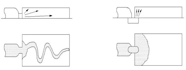
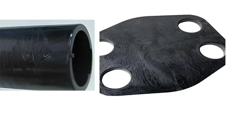
Jetting manifests as distinct snake-like or worm-like patterns on the part surface. These marks differ from internal flow lines because they remain visible on the exterior finish.
- Location: Defects typically appear directly downstream from the gate entry point.
- Severity: Mild cases show faint ripples, while severe instances display deep, folded layers.
Mechanisms Behind Jetting Formation
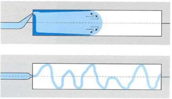
Jetting occurs when high-velocity melt shoots into a large cavity without touching the mold walls. The polymer stream cools and solidifies in mid-air before folding over itself.
- Velocity Issue: Injection speed exceeds the material’s ability to adhere to the mold surface.
- Thermal Shock: The free-streaming jet loses heat rapidly, creating a skin that prevents proper welding.
This process creates discrete layers rather than a homogeneous melt front. Subsequent material pushes against this cooled skin, locking in the defect.
Structural and Functional Compromises
Jetting significantly reduces tensile strength at the defect site due to poor molecular bonding. These weak points are prone to cracking under minimal mechanical stress.
- Strength Loss: Tensile strength can drop by 30-50% across the jetted line.
- Air Traps: Folded layers often entrap air, leading to voids or burn marks.
Long-term durability suffers in load-bearing applications due to these structural discontinuities. Aesthetic flaws also negatively impact consumer perception of product quality.
Diagnosing the Root Cause: Mold Design vs. Processing Parameters
Evaluating Mold Design Flaws
Gate dimensions must align with part geometry to prevent flow instability. A gate thickness below 50% of the adjacent wall thickness often causes excessive shear heating.
- Gate Placement: Position gates opposite solid cores, not open cavities, to avoid jetting.
- Flow Geometry: Avoid abrupt transitions in runner diameter; use gradual tapers to maintain laminar flow.
Runner system balance directly impacts fill consistency across multi-cavity tools. Asymmetrical runners cause pressure drops, leading to uneven packing and dimensional variance.
| Feature | Ideal Specification | Risk of Deviation |
|---|---|---|
| Gate Thickness | 50-80% of wall thickness | High shear, material degradation |
| Runner Transition | Gradual taper (1:10 ratio) | Turbulent flow, air traps |
| Cavity Balance | ±2% flow length difference | Uneven part weight, warpage |
Assessing Processing Parameter Errors
Injection speed must match the gate’s ability to dissipate heat. Excessive speed through a small gate generates frictional heat, lowering viscosity and causing jetting.
Melt temperature inconsistencies alter flow behavior unpredictably. A variance of ±10°C can significantly change viscosity, affecting fill patterns.
- Hold Pressure: Insufficient packing pressure fails to compensate for shrinkage, causing sink marks.
- Recovery Time: Inconsistent shot sizes indicate poor plastication or check ring wear.
Machine recovery time verifies the consistency of the melt cushion. A fluctuating cushion suggests unstable processing conditions rather than mold issues.
Differentiating Between Design and Process Origins
Permanent tooling issues persist despite optimal parameter adjustments. If jetting occurs at all reasonable injection speeds, the gate location or size is likely flawed.
Process adjustments fail when the physical flow path promotes turbulence. Scientific molding principles help isolate these variables by decoupling filling from packing.
| Indicator | Likely Cause | Action |
|---|---|---|
| Defect persists at low speed | Mold Design | Modify gate size or location |
| Defect resolves with slower speed | Process Parameter | Adjust injection profile |
| Inconsistent shot volume | Machine/Material | Check check ring or dryer |
Correlate specific machine alarms with defect timing. Jetting during the initial fill phase points to velocity control, while late-stage defects suggest packing issues.
Troubleshooting Jetting Through Process Optimization
Adjusting Injection Speed Profiles
Implement a multi-stage injection profile to control flow dynamics. Start with a low initial speed (10-20 mm/s) to ensure the melt contacts the mold wall immediately.
- Stage 1: Low speed through the gate to prevent free-stream jetting.
- Stage 2: Ramp up speed once the gate area is filled and flow is established.
Switch from velocity to pressure control (V/P switchover) at 95-98% cavity fill. This timing prevents over-packing while ensuring complete part formation.
Optimizing Melt and Mold Temperatures
Raise the melt temperature within the material’s safe range to reduce viscosity. Lower viscosity decreases shear stress, allowing smoother flow through the gate.
| Parameter | Typical Adjustment | Effect on Jetting |
|---|---|---|
| Melt Temp | +10°C to +20°C | Reduces viscosity and shear heat |
| Mold Temp | Increase slightly | Delays skin formation |
Balance mold temperature to prevent premature skin formation on the melt front. Ensure barrel zones maintain a consistent gradient to avoid thermal degradation.
Fine-Tuning Pressure and Backpressure
Apply sufficient backpressure (5-15 bar) during plastication to improve melt homogeneity. This ensures consistent viscosity and reduces the likelihood of unstable flow.
Optimize hold pressure to pack the part without inducing excessive shear stress. Monitor the cushion size, keeping it between 3-5 mm for process stability.
- Test parameters iteratively in small increments.
- Validate changes with short shots to observe flow patterns.
Best Practices for Gate Design and Mold Geometry Prevention
Strategic Gate Placement and Type Selection
Position gates to impinge on mold walls or cores rather than injecting directly into open cavities. This technique dissipates kinetic energy and prevents jetting defects.
Select gate types based on part geometry and automation needs. Submarine gates enable automatic degating, while fan gates reduce shear stress on sensitive materials.
| Gate Type | Primary Benefit | Typical Application |
|---|---|---|
| Fan Gate | Low shear rate | Wide, flat parts |
| Tab Gate | Stress isolation | Optical or cosmetic surfaces |
| Submarine | Automatic degating | High-volume production |
Modifying Gate Geometry and Dimensions
Increase gate land length to stabilize flow front progression. A longer land (typically 0.5–1.5 mm) helps dampen flow instability before entering the cavity.
Optimize gate thickness to control shear heating and viscosity. Gradual transitions from runner to gate prevent sudden pressure drops and material degradation.
- Shear Rate Control: Keep shear rates below 100,000 s⁻¹ for most thermoplastics.
- Transition Design: Use a tapered approach angle of 15–30 degrees to smooth flow entry.
Cavity and Runner System Considerations
Ensure uniform wall thickness to promote balanced filling and minimize warpage. Design runners with adequate diameter to reduce pressure drop across the system.
Incorporate strategic venting to allow air escape during high-speed fills. Use simulation software to predict flow patterns and identify trapped air pockets before tooling.
| Parameter | Recommended Value | Purpose |
|---|---|---|
| Vent Depth | 0.02–0.04 mm | Air escape without flash |
| Runner Diameter | 6–10 mm (typical) | Minimize pressure loss |
| Wall Thickness Variation | < 10% | Reduce internal stresses |
Distinguishing Jetting from Other Surface Defects
Jetting vs. Splay (Silver Streaks)
Jetting appears as distinct, snake-like folds on the surface. Splay manifests as fine, radial silver streaks spreading from the gate.
- Root Cause: Jetting results from high-velocity injection into open space. Splay stems from moisture vaporization or material degradation.
- Diagnostic Test: Use a moisture analyzer to check resin levels. Target values should remain below 0.02% for most hygroscopic plastics.
| Defect Type | Visual Pattern | Primary Cause | Corrective Action |
|---|---|---|---|
| Jetting | Snake-like ridges | High injection speed | Reduce speed; increase gate size |
| Splay | Radial silver streaks | Moisture/Volatiles | Dry material; lower melt temp |
Jetting vs. Gate Blush
Gate blush presents as a cloudy or hazy area immediately adjacent to the gate. It differs from jetting, which creates physical ridges rather than surface haze.
Shear heating during injection causes localized material degradation. This thermal stress creates the opaque appearance known as blush.
- Solution: Polish the gate land to reduce flow resistance.
- Adjustment: Lower injection speed to minimize shear rates. Typical shear rates should stay below 10,000 s⁻¹ for sensitive resins.
Jetting vs. Flow Lines and Weld Lines
Flow lines appear as concentric rings indicating cooling variations. Weld lines form linear junctions where separate flow fronts meet.
Jetting is distinct because it involves uncontrolled fountain flow. It does not require two meeting fronts like a weld line.
- Visual Cue: Look for cold slugs at the start of a flow line. Jetting lacks this specific stagnation point.
- Correction: Increase mold temperature to improve flow fusion. Adjust gate location to prevent direct impingement on core pins.