
Understanding the Science Behind Injection Molding Burn Marks
The Mechanism of Diesel Effect and Thermal Degradation
Trapped air acts as an insulator within the mold cavity. As the melt front advances, it compresses this air adiabatically.
This compression raises air temperature to over 1000°F (538°C) in microseconds. Such extreme heat ignites the polymer instead of melting it.
- Ignition Threshold: Temperatures exceed the auto-ignition point of most thermoplastics.
- Timeframe: Heating occurs almost instantaneously during the final fill phase.
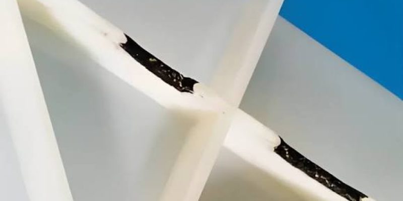
Thermal degradation breaks polymer chains into carbon residues. This process creates the characteristic black specks or streaks.
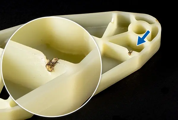
True burn marks differ from general material degradation. Contamination causes random discoloration, while the diesel effect follows airflow paths.
| Defect Type | Primary Cause | Visual Pattern |
|---|---|---|
| Diesel Burn | Trapped Air Compression | End-of-fill, opposite gate |
| Degradation | Overheating in Barrel | Random streaks, entire part |
| Contamination | Foreign Material | Isolated spots, varied colors |
Visual Identification and Classification of Defects
Black burn marks typically appear at the end of the fill path. They are common near gates or where thick sections transition to thin ones.
These locations trap air just before the mold vents release pressure. The burn mark signals where the air pocket was compressed.
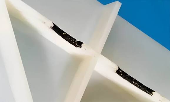
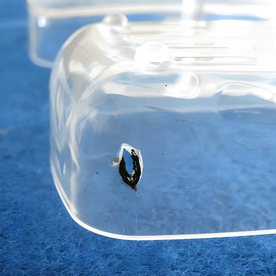
- Location: Farthest point from the gate or last area to fill.
- Appearance: Dark brown to black discoloration on the surface.
Splay presents as silver streaks rather than black burns. Moisture or volatiles cause splay, not adiabatic compression.
Jetting burns occur when melt shoots across the cavity. Venting burns appear where air escapes through parting lines.
| Defect | Pattern | Position |
|---|---|---|
| Jetting Burn | Snake-like line | Near gate entry |
| Venting Burn | Linear streak | Along parting line/vents |
| Splay | Silver streaks | Random or flow direction |
Severity ranges from superficial discoloration to structural pitting. Surface burns may only affect aesthetics and can sometimes be polished.
Deep burns compromise mechanical integrity and create stress concentrators. These parts often fail under load and must be scrapped.
- Minor: Surface discoloration only; part may be salvageable.
- Major: Pitting or charring; structural weakness requires rejection.
Diagnosing Root Causes: Machine, Mold, and Material
Machine Settings and Processing Parameters
Injection speed directly affects air entrapment within the mold cavity. Excessive speed prevents air from escaping through vents before the melt front seals them off.
High barrel temperatures cause pre-degradation of the polymer chain. Look for discoloration or black specks as primary indicators of thermal breakdown.
- Back Pressure: High settings increase shear heat, raising melt temperature unpredictably.
- Screw Rotation: Fast rotation generates frictional heat, risking material degradation before injection.
Residence time in the barrel must match the material’s thermal stability limit. Prolonged cycle times expose resin to heat for too long, causing chemical breakdown.
| Parameter | Risk Factor | Typical Constraint |
|---|---|---|
| Injection Speed | Air trapping | Adjust based on part thickness |
| Barrel Temp | Thermal degradation | Stay within manufacturer range |
| Residence Time | Material breakdown | Keep under 5-10 minutes typically |
Mold Design and Venting Efficiency
Vent dimensions must match the specific viscosity of the resin being processed. Standard vent depths usually range from 0.01 mm to 0.03 mm depending on material flow.
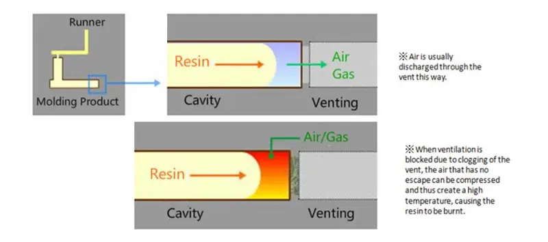
Accumulated residue in vents blocks air escape paths effectively. Regular maintenance is required to remove carbonized material or mold release buildup.
- Gate Location: Poor placement forces air into blind spots or corners.
- Runner Balance: Unbalanced fills cause air traps in slower-filling cavities.
Ensure runner systems are balanced to promote uniform filling. Uneven flow rates lead to localized air pockets and potential burn marks.
| Issue | Cause | Solution |
|---|---|---|
| Blocked Vents | Residue buildup | Clean vents every shift |
| Air Traps | Poor gate location | Redesign gate position |
| Uneven Fill | Unbalanced runners | Balance runner geometry |
Material Properties and Handling
Certain resins like PVC and POM are highly sensitive to thermal degradation. These materials require strict temperature control to prevent rapid breakdown.
Moisture in resin turns to steam during processing, causing burns. Always verify moisture content is below 0.02% for hygroscopic materials.
- Regrind Usage: Excessive recycled material reduces thermal stability.
- Additives: Colorants and flame retardants can lower ignition thresholds.
Limit regrind usage to maintain consistent flow and thermal properties. High percentages of regrind often introduce inconsistent melting behaviors.
Check additive interactions before processing new compounds. Some flame retardants decompose at lower temperatures than the base resin.
| Material Factor | Impact | Mitigation Strategy |
|---|---|---|
| Moisture | Steam burns | Dry resin to <0.02% moisture |
| Regrind | Instability | Limit to 10-20% max |
| Additives | Lower ignition point | Reduce processing temps |
Immediate Troubleshooting and Parameter Adjustments
Optimizing Injection Speed and Pressure
Implement multi-stage injection profiles to control flow dynamics. Slow the final fill stage to 10-20% of peak speed. This allows trapped air to escape through vents before the cavity seals.
Reduce peak injection speed to balance cycle time and quality. High speeds generate excessive shear heat, leading to material degradation. Find the lowest speed that still prevents premature freezing.
Adjust hold pressure to ensure proper packing without over-packing. Excessive pressure forces degraded material into surface details. Monitor cavity pressure sensors to set precise hold values.
Use decoupled molding techniques for superior process control. Separate the fill, pack, and hold phases distinctly. This isolation prevents velocity changes from affecting packing pressure.
Temperature and Cooling Modifications
Lower the melt temperature in 5°C increments. Identify the minimum viable processing temperature for the specific resin. This reduces the risk of thermal degradation and burning.
Adjust nozzle and front-zone temperatures to prevent localized overheating. Keep these zones 5-10°C lower than the rear barrel. This prevents drooling and heat buildup at the gate.
Enhance mold cooling to solidify the skin layer faster. Increase coolant flow rate to maintain turbulent flow. Faster heat extraction minimizes the time material spends in a molten state.
Monitor shear heat by adjusting screw RPM and back pressure. High rotational speeds generate internal friction heating. Reduce RPM to keep shear heat within safe limits for the polymer.
| Parameter | Typical Adjustment | Engineering Reason |
|---|---|---|
| Melt Temp | -5°C steps | Minimizes thermal degradation |
| Nozzle Temp | -5 to -10°C vs Barrel | Prevents gate burning |
| Screw RPM | Reduce by 10-15% | Lowers shear heating |
Systematic Process of Elimination
Perform short-shot testing by filling the mold to 90-95%. This reveals exactly where air gets trapped before the cavity closes. Observe the flow front progression visually.
Inspect vent lands for black residue after short shots. Dark deposits indicate compressed air burning the material. Clean or deepen vents if residue is present.
Log all parameter changes systematically during troubleshooting. Documenting variables isolates the specific cause of the defect. This data prevents reverting to ineffective settings.
Run swap tests with known good material batches. This rules out resin-specific issues like moisture or contamination. If defects persist, the problem lies in the process or tooling.
Preventive Design Guidelines and Mold Maintenance
Strategic Venting Solutions
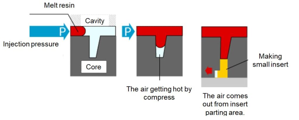
Proper vent placement is critical for air evacuation. Position vents at the end of fill paths and along weld lines to prevent trapped air pockets.
Active vacuum systems enhance venting in complex geometries. These systems actively pull air out before injection, reducing burn marks by up to 90% in deep ribs.
| Polymer Family | Vent Depth (mm) | Vent Land Length (mm) |
|---|---|---|
| Polyethylene (PE) | 0.025 – 0.038 | 1.5 – 2.5 |
| Polycarbonate (PC) | 0.013 – 0.025 | 1.0 – 1.5 |
| Nylon (PA6/66) | 0.013 – 0.025 | 1.0 – 1.5 |
Permeable steel inserts offer a solution for hard-to-vent areas. These porous metals allow air to pass through while retaining molten plastic, ideal for blind cores.
Gate and Runner System Optimization
Enlarging gate dimensions reduces shear heat generation. This adjustment stabilizes the flow front and minimizes material degradation at the entry point.
Switching gate types alters flow dynamics significantly. Submarine or fan gates distribute stress better than standard edge gates, reducing jetting risks.
Runner balancing ensures uniform fill rates across cavities. Unbalanced runners cause air trapping in slower-filling cavities, leading to inconsistent part quality.
Cold slug wells capture degraded material effectively. Design these wells with a reverse taper to pull the cold front away from the main cavity during injection.
Routine Maintenance and Cleaning Protocols
Regular vent cleaning prevents carbon buildup. Use brass brushes and approved solvents every 5,000 to 10,000 shots to maintain vent efficiency.
Inspect parting lines for damage or misalignment. Even minor shifts can block venting paths, causing flash or incomplete filling.
Ejector pins serve as auxiliary vents when fitted correctly. Keep pin holes clean and lubricated to ensure air escapes without sticking.
Apply low-friction coatings like DLC or PTFE. These treatments reduce release force and improve flow, indirectly aiding in consistent mold ventilation.
Advanced Techniques for Persistent Burn Mark Issues
Alternative Molding Processes
Gas-assisted injection molding uses nitrogen pressure to push the melt front. This technique eliminates air traps that cause burning in thick sections.
Compression molding reduces shear stress by closing the mold during injection. The lower shear rates prevent localized overheating of the polymer.
| Process | Key Mechanism | Primary Benefit |
|---|---|---|
| Gas-Assisted | Nitrogen pressure | Eliminates air traps |
| Compression | Mold closure during fill | Reduces shear heat |
| Co-injection | Clean skin layer | Hides core defects |
| Microcellular | Foaming agents | Lowers viscosity |
Co-injection molding creates a clean skin layer over the core material. This covers potential burn marks located in the internal structure.
Microcellular foaming alters viscosity and flow characteristics significantly. The reduced viscosity lowers the risk of gas trapping during fill.
Hardware and Technology Upgrades
High-performance mixing screws reduce shear heat while maintaining material homogeneity. Look for designs with lower compression ratios to minimize frictional heating.
Hot runner systems require precise temperature control zones to prevent stagnation. Independent PID loops for each nozzle ensure consistent melt temperature within ±1°C.
- Cavity Pressure Sensors: Detect air traps instantly by monitoring pressure spikes.
- Automated Vent Cleaning: Uses ultrasonic or laser methods to remove carbon buildup.
Real-time process monitoring installs sensors directly into the mold cavity. These devices detect abnormal pressure signatures associated with air traps.
Automated vent cleaning systems integrate into regular maintenance routines. Ultrasonic cleaning removes debris without damaging delicate vent lands.
When to Redesign the Part or Mold
Evaluate wall thickness variations to identify abrupt transitions. These features often cause turbulent flow and subsequent air entrapment.
Add relief features such as small overflow wells near end-of-fill areas. These wells capture burnt material away from visible cosmetic surfaces.
| Design Issue | Solution | Engineering Constraint |
|---|---|---|
| Thick-to-thin transition | Add fillets | Minimize cycle time impact |
| End-of-fill burns | Overflow wells | Increase material usage |
| Complex geometry | Iterative mold changes | Higher tooling cost |
Collaborate with mold makers for iterative design changes on complex geometries. Inherent trapping risks often require physical modifications to the steel.
Perform a cost-benefit analysis before committing to major retooling. Process tweaks are insufficient when burn marks persist despite optimal parameters.