Fundamentals and Strategic Advantages of Snap-Fit Joints
What Are Injection Molded Snap Fits?
Snap-fit joints are integral features molded directly into plastic parts. They create mechanical interlocks that join components without external hardware.

These designs replace screws, clips, or adhesives entirely. This consolidation reduces part count and simplifies the bill of materials.
The joint relies on elastic deformation during assembly. The cantilever beam bends temporarily and returns to its original shape to lock.
Key Benefits Over Screws, Adhesives, and Ultrasonic Welding
Eliminating separate fasteners lowers both material and labor costs. Assembly time drops significantly because no tools or curing periods are required.
Snap fits provide a clean exterior aesthetic by hiding connection points. Users see seamless surfaces rather than visible screw heads or weld lines.
Disassembly is straightforward for repair or recycling purposes. This supports sustainable design practices and easier battery replacement in consumer electronics.
Potential Drawbacks and Limitations to Consider
Plastic materials suffer from creep and stress relaxation over time. This can reduce holding force and lead to joint failure under constant load.
| Factor | Impact on Snap Fit |
|---|---|
| Creep | Gradual loss of retention force |
| Fatigue | Failure after repeated assembly cycles |
| Temperature | Reduced stiffness at elevated temps |
Tooling requires high precision to maintain tight tolerances. Small deviations in mold dimensions can cause assembly issues or weak locks.
Standard snap fits have limited reusability compared to screws. High-load or high-vibration environments often require additional locking features.
Choosing the Right Geometry: Types of Snap-Fit Designs
Cantilever Snap Fits: The Industry Standard
The cantilever snap fit consists of a flexible beam, a retention hook, and an undercut. This simple geometry allows for easy molding and predictable deflection behavior.
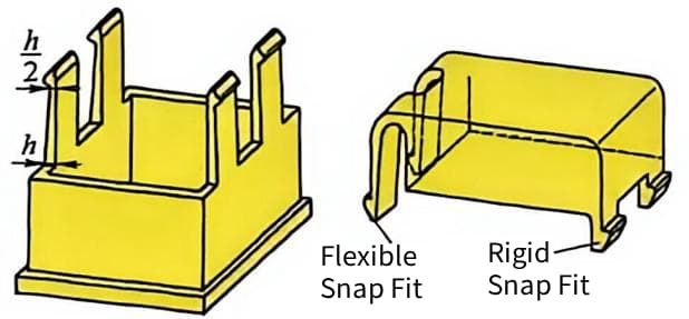
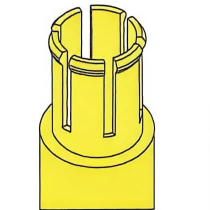
Annular cantilever snap fits share some similarities with annular snap-fit joints. However, due to the presence of slots, the load is primarily in the form of bending. Therefore, I would say this type of joint is classified as a cantilever snap fit.
By matching a rigid hole on one side with a cantilever snap fit on the other, an economical and reliable snap-fit joint can be achieved. This design is particularly effective for assembling similar-shaped housings that require easy separation.
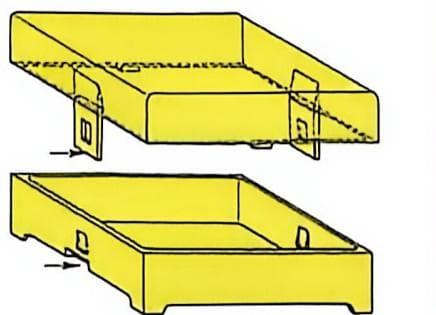
Annular (Ring) Snap Fits for Cylindrical Assemblies
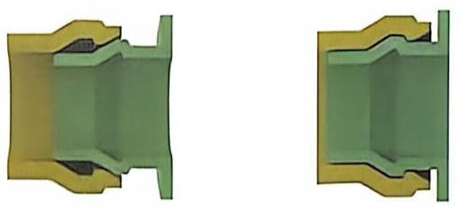
Annular snaps are ideal for pipe connections, caps, and cylindrical housings. They rely on uniform radial expansion to create a secure seal or lock.
Stress distribution occurs evenly around the circumference, reducing local failure points. This geometry minimizes the risk of crack propagation compared to point-load cantilevers.
L-Shaped and U-Shaped Snap Fits for Specialized Loads
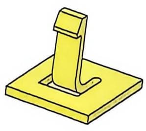
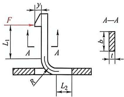
L-shaped snap fits are formed by designing slots in the base wall. Compared with standard cantilever snaps, they effectively increase the beam length and flexibility, allowing design engineers to keep strain below the allowable strain value of the selected material during assembly.
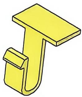
U-shaped snap fits are another approach to increasing the effective beam length within a limited space. A U-shaped snap fit design typically integrates the latch feature into the outer edge of the component, thereby eliminating the need for sliders in the mold unless slots on the protruding side wall are acceptable.
Engineering Precision: Calculations and Design Guidelines
Critical Dimensions: Undercut, Deflection, and Retention
Designers must calculate the maximum permissible undercut by referencing the material’s allowable strain limit. Exceeding this limit during assembly causes permanent deformation or stress whitening.
For L-shaped snap fits, the deformation calculation is as follows:
$$
L_2 = \frac{\frac{6}{\varepsilon} \, y t (L_1 + R)\;-\;4L_1^3\;-\;3R\left(2\pi L_1^2 + \pi R^2 + 8L_1R\right)}{12(L_1 + R)^2}
$$
$$
y = \frac{F}{12EI}\left[4L_1^3 + 3R\left(2\pi L_1^2 + \pi R^2 + 8L_1R\right) + 12L_2 (L_1 + R)^2\right]
$$
Where
- $\varepsilon$ is the material allowable strain;
- $E$ is the flexural modulus;
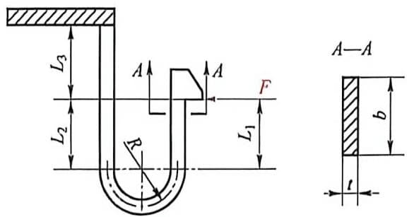
- $I$ is the moment of inertia; and other letters correspond to the labels in the relevant figures.
For U-shaped snap fits, the deformation calculation is as follows:
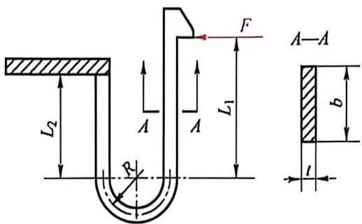
a) The snap fit protrudes above the mounting surface.
$$
y = \frac{\varepsilon}{9(L_1 + R)}\Big[6L_1^3 + 9R\big(L_1(2\pi L_1 + 8R) + \pi R^2\big) + 6L_2\big(3L_1^3 – 3L_1L_2 + L_2^2\big)\Big]
$$
or
$$
y = \frac{F}{18E}\Big[6L_1^3 + 9R\big(L_1(2\pi L_1 + 8R) + \pi R^2\big) + 6L_2\big(3L_1^3 – 3L_1L_2 + L_2^2\big)\Big]
$$
b) The snap fit is recessed below the mounting surface.
$$
y = \frac{\varepsilon}{3(L_1 + R)t}\Big[4L_1^3 + 2L_3^3 + 3R\big(L_1(2\pi L_1 + 8R) + \pi R^2\big)\Big]
$$
or
$$
y = \frac{F}{6EI}\Big[4L_1^3 + 2L_3^3 + 3R\big(L_1(2\pi L_1 + 8R) + \pi R^2\big)\Big]
$$
Material Properties Impact on Design Calculations
Glass-filled resins increase stiffness but drastically reduce elongation at break. This brittleness makes them poor candidates for large-undercut snap fits unless designed with very short beams.
To intuitively understand material performance, Table below lists the allowable strains for some commonly used materials for engineers to reference during design.
| Material | Allowable Strain (Unfilled) | Allowable Strain (30% Glass Fiber) |
|---|---|---|
| PEI | 9.8% | — |
| PC | 4%-9.2% | — |
| POM | 7% | 2.0% |
| PA6 | 8% | 2.1% |
| PBT | 8.8% | 2.0% |
| PC/PET | 5.8% | — |
| ABS | 6%-7% | — |
| PET | — | 1.5% |
Practical Application: Step-by-Step Design and Case Studies
Step-by-Step Workflow for Designing a Snap-Fit Enclosure
Start by defining the assembly force limits and expected load cases. Determine if the joint requires frequent disassembly or permanent locking.
Select a material with suitable flexibility and fatigue resistance, such as Polycarbonate or ABS. Draft initial geometry based on standard beam lengths and thickness ratios.
| Step | Action | Key Parameter |
|---|---|---|
| 1 | Define Requirements | Assembly Force < 50 N |
| 2 | Select Material | Strain Limit < 4% |
| 3 | Hand Calculations | Beam Length/Thickness Ratio > 10:1 |
Perform hand calculations to estimate preliminary dimensions using simple beam theory. Ensure the maximum strain stays below the material’s elastic limit.
Create the CAD model with generous fillets at the beam root to reduce stress concentration. Apply draft angles of 1–3 degrees to facilitate mold release.
Run FEA simulations to verify stress distribution and deflection under load. Adjust geometry iteratively until safety factors meet industry standards.
Troubleshooting Common Snap-Fit Failures
White stress marks indicate excessive strain during assembly or operation. This visual cue suggests the material has yielded beyond its elastic limit.
- Symptom: Whitening at the beam root.
- Cause: Strain exceeds 4-6% for most thermoplastics.
Reduce the undercut depth or increase the beam length to lower strain. A longer beam deflects more easily, reducing stress at the base.
Loose fits often result from insufficient undercut depth or material shrinkage. Adjust the CAD model to compensate for specific material shrinkage rates.
| Issue | Root Cause | Fix |
|---|---|---|
| White Marks | Excessive Strain | Increase beam length |
| Loose Fit | Low Undercut | Increase undercut by 0.1mm |
| Breakage | Sharp Lead-in | Increase angle to 30-45° |
Prevent breakage by optimizing lead-in angles to 30–45 degrees. Applying a silicone-based lubricant can also reduce friction during assembly.