Dimensional Ratios for Structural Integrity and Sink Mark Prevention
Optimal Rib Thickness to Wall Thickness Ratio
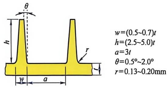
To reduce sink marks on the surface opposite ribs, the rib wall thickness should follow specific guidelines relative to the nominal wall thickness. Adhering to these ratios prevents material accumulation that leads to visible sink marks on cosmetic surfaces.
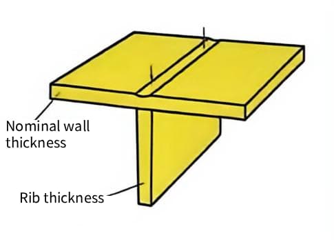
Material crystallinity significantly influences the ideal thickness ratio due to varying shrinkage rates. Please see the table below for details. For high-gloss critical surfaces, even thinner ribs may be necessary to avoid affecting appearance.
| Material Type | Example Resins | Recommended Ratio (%) | Primary Risk if Exceeded |
|---|---|---|---|
| Semi-Crystalline | PP, PA6, POM | 40–50% | Severe sink marks, internal voids |
| Amorphous | ABS, PC, PS | 50–60% | Moderate sink marks, longer cycle time |
To hide potential sink marks, ribs can be positioned opposite character markings or steps.
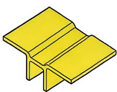
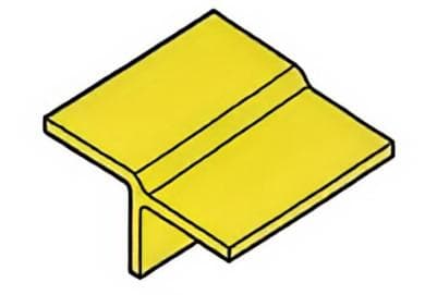
Excessive rib thickness creates hot spots that drastically increase cooling time and promote internal voiding. These thermal inconsistencies compromise structural integrity and extend production cycles unnecessarily. Notably, thin-walled parts (1.0 mm or less) can often withstand higher rib thickness percentages; in such cases, it is recommended that the rib thickness equal the wall thickness to ensure optimal strength and moldability. However, very thin ribs may suffer from incomplete filling due to insufficient plastic melt flow.
Rib Height and Stability Guidelines
It is recommend that limit rib height to no more than three times the nominal wall thickness to ensure mold core stability. Taller ribs increase the risk of damage during ejection. High aspect ratios reduce stiffness relative to the added material cost and weight. Engineers should prioritize multiple shorter ribs over a single tall rib to distribute stress evenly.
- Structural Benefit: Multiple ribs increase moment of inertia without exceeding height limits.
- Mold Longevity: Shorter cores resist bending forces, reducing maintenance frequency.
- Ejection Safety: Lower ribs minimize friction and drag marks during part removal.
The relationship between rib height and core pin diameter is critical for preventing breakage. Thin, tall cores are prone to fatigue failure under high injection pressures.
Spacing and Pitch Considerations
Maintain a minimum distance between ribs equal to three times the nominal wall thickness. This spacing allows adequate coolant flow around mold cores to prevent localized heat buildup. If ribs are too close together, they form thin-wall areas that are difficult to cool, negatively impacting product quality and productivity.
Insufficient spacing leads to differential cooling rates, causing warpage and dimensional instability. Proper pitch ensures uniform heat extraction across the entire part geometry.
| Structure Type | Recommended Spacing | Cooling Implication | Cosmetic Impact |
|---|---|---|---|
| Linear Ribs | ≥ 3x Wall Thickness | Uniform linear heat transfer | Minimal rib shadow |
| Grid Patterns | ≥ 3.5x Wall Thickness | Complex heat dissipation paths | Potential cross-hatch sinking |
Avoid “rib shadow” effects by ensuring ribs do not cluster near thick sections or corners. Visible depressions on the cosmetic surface often result from poor spacing rather than just thickness issues. Strategic placement reduces the need for post-molding finishing operations. Consistent pitch simplifies mold machining and improves overall production efficiency.
Designing Press-fit Rib for Assemblies and Ejection
Geometry and Interference Fit Principles
Press-fit rib function as localized deformation zones that create gas-tight or fluid-tight seals. They compress upon assembly to fill micro-gaps between mating components. While press-fit technology can theoretically be used with any thermoset or thermoplastic, it is significantly easier to apply to plastics with better toughness.
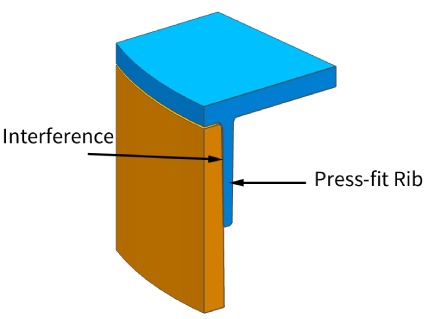
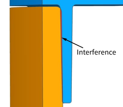
Interference values depend heavily on material stiffness. see the table below for details.
The design strain value—especially in long-term applications where stress relaxation may occur—should not exceed 10%–40% of the fracture strain.
| Material Type | Typical Interference (mm) | Interference In Long Term Application |
|---|---|---|
| Polypropylene (PP) | 0.15 – 0.25 | 0.06 – 0.1 |
| Acrylonitrile Butadiene Styrene (ABS) | 0.10 – 0.20 | 0.04 – 0.08 |
| Thermoplastic Elastomer (TPE) | 0.20 – 0.40 | 0.04 – 0.08 |
These stress and strain considerations also apply to press-fit assembly.
Draft Angles for Ejection and Assembly
Standard draft angles for press-fit rib range from 1 to 2 degrees per side. This facilitates mold release while maintaining sufficient contact area for sealing. Excessive draft reduces the effective interference fit. Engineers must balance ejection ease with the required compression ratio.
| Draft Angle (deg/side) | Ejection Force | Seal Contact Area | Risk of Stick-off |
|---|---|---|---|
| 0.5 | High | Maximum | Low |
| 1.0 | Moderate | High | Low |
| 2.0 | Low | Moderate | Minimal |
| >3.0 | Very Low | Low | None |
Draft angles alter the radial contact profile during assembly. A tapered rib creates a progressive interference fit rather than an instantaneous snap. To maintain seal integrity, design the rib height to compensate for angular loss. Ensure the base width provides enough material support against shear stress.
Material Selection for Crush Rib Applications
Polypropylene (PP), Polyethylene (PE), and Thermoplastic Elastomers (TPE) offer superior elastic recovery. These materials return to their original shape after compression, maintaining long-term seal pressure. Avoid brittle resins like Polystyrene (PS) or unfilled Polycarbonate (PC). These materials are prone to cracking under the high localized stress of press-fit rib.
Surface finish directly influences assembly friction and seal quality. A smooth finish (Ra < 0.8 µm) reduces insertion force and prevents galling. Rough surfaces can tear soft elastomers during press-fit operations. Polish mold cores in the direction of ejection to minimize drag.
Strategic Rib Placement and Orientation for Stiffness and Warpage Control
Maximizing Stiffness Through Orientation
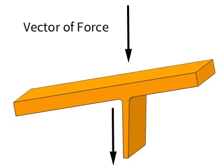
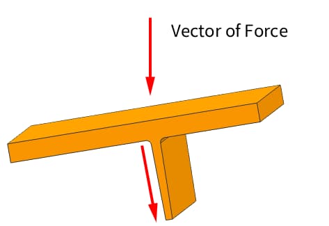
Align ribs parallel to the primary vector of applied force. This orientation maximizes the moment of inertia and minimizes deflection under load.
- Implement cross-ribbing or grid patterns to resist torsional forces effectively.
- Isolated parallel ribs often fail to prevent twisting in large planar sections.
Account for material anisotropy in glass-filled polymers like 30% GF-PA66. Flow-induced fiber alignment creates directional stiffness variations that must match the rib layout.
| Material Type | Primary Stiffness Direction | Recommended Rib Strategy |
|---|---|---|
| Unfilled Resin | Isotropic | Symmetrical grid or load-aligned |
| Glass-Filled | Anisotropic (Flow Direction) | Align ribs with mold flow paths |
Utilize Finite Element Analysis (FEA) to validate deflection predictions before tooling. Simulations identify weak axes where additional ribbing is required to meet safety factors.
Minimizing Warpage Through Symmetrical Design
Balance rib placement around the part’s center of gravity to equalize shrinkage stresses. Asymmetrical layouts cause uneven cooling rates, leading to significant bowing or twisting.
Maintain a consistent rib-to-wall thickness ratio, typically between 0.5 and 0.7 times the nominal wall. Abrupt thickness changes create internal voids and differential cooling zones.
- Distribute rib density evenly across the part geometry to avoid localized stress concentrations.
- Avoid clustering multiple ribs in one area while leaving adjacent sections unsupported.
Position gates to ensure uniform melt front advancement across ribbed sections. Improper gating can cause preferential packing on one side, exacerbating warpage issues.
Cycle Time Optimization via Rib Layout
Recognize that ribs act as heat sinks due to their increased mass relative to the base wall. Complex or deep ribs require longer cooling times to solidify completely.
Design rib bases with adequate radii (minimum 0.5mm) to facilitate heat transfer into the mold steel. Sharp corners insulate the core material, creating persistent hot spots.
- Space ribs at least 2-3 times the nominal wall thickness apart to allow coolant channel proximity.
- Clustered ribs prevent effective mold cooling, forcing extended cycle times to prevent ejection defects.
Evaluate the trade-off between theoretical maximum stiffness and production efficiency. Adding marginal stiffness via excessive ribbing often yields diminishing returns compared to the cost of increased cycle time.
| Design Feature | Impact on Cooling | Manufacturing Consequence |
|---|---|---|
| Deep, Narrow Ribs | Poor heat dissipation | Increased cycle time, sink marks |
| Spaced, Moderate Ribs | Uniform cooling | Optimized cycle time, flat parts |
Material-Specific Rib Design Guidelines for ABS, Nylon, and Polycarbonate
Rib Design for Amorphous Plastics (ABS and Polycarbonate)
Amorphous resins like ABS benefit from lower viscosity during flow, allowing for thinner rib walls. Maintain a rib-to-wall thickness ratio of 0.5 to 0.6 to prevent sink marks on the cosmetic surface.
Polycarbonate requires careful handling due to its high stiffness and susceptibility to stress cracking. Avoid sharp internal corners at the rib base by using a fillet radius of 0.5 to 0.75 times the wall thickness.
Cooling rates significantly impact dimensional stability in amorphous materials. Uniform cooling prevents differential shrinkage, ensuring rib height remains within ±0.1 mm tolerance.
| Parameter | ABS Recommendation | Polycarbonate Recommendation |
|---|---|---|
| Rib/Wall Ratio | 0.5 – 0.6 | 0.5 – 0.6 |
| Draft Angle | 0.5° – 1.0° per side | 1.0° – 1.5° per side |
| Base Fillet Radius | 0.25T – 0.5T | 0.5T – 0.75T |
Rib Design for Semi-Crystalline Plastics (Nylon/PA)
Nylon exhibits high shrinkage rates, often between 1.5% and 2.5%, due to crystallization. Reduce rib thickness to 40–50% of the main wall thickness to mitigate volumetric shrinkage defects.
Moisture absorption causes Nylon parts to swell post-molding, affecting assembly fits. Design ribs with slightly tighter tolerances initially to account for hygroscopic expansion up to 1.5% in saturated conditions.
Balanced ribbing is critical to prevent warpage caused by uneven crystallization. Symmetrical rib placement ensures uniform cooling and minimizes internal residual stresses.
- Shrinkage Compensation: Account for anisotropic shrinkage in flow versus cross-flow directions.
- Gate Location: Position gates to ensure uniform packing pressure across all rib structures.
General Material Property Impacts on Rib Geometry
The modulus of elasticity dictates the required rib height for structural rigidity. Higher modulus materials allow for shorter ribs, while flexible resins require increased height or additional support ribs.
Filler materials like glass fiber improve strength but degrade surface finish at rib bases. Limit fiber length to minimize orientation issues and maintain a smooth transition at the rib root.
Thermal conductivity variations affect cooling time and cycle efficiency. Materials with low conductivity, such as unfilled polycarbonate, require longer cooling times to solidify thick rib sections properly.
| Material Factor | Design Adjustment | Engineering Reason |
|---|---|---|
| High Modulus | Reduce rib height | Maintains stiffness with less material |
| Glass Filled | Increase draft angle | Prevents fiber drag and surface tearing |
| Low Conductivity | Extend cooling time | Ensures core solidification without voids |
Mitigating Common Manufacturing Defects in Ribbed Parts
Preventing Gas Traps and Voids
Air entrapment frequently occurs at the intersection of ribs and main walls. This happens because melt flow fronts converge rapidly in these thick-to-thin transitions.
- High-Risk Zones: Focus venting efforts on rib bases where wall thickness exceeds 60% of the nominal wall.
- Vent Design: Implement vents with a depth of 0.01–0.02 mm to allow air escape without material flash.
Deep ribs require specialized venting strategies to prevent burn marks and voids. Standard parting line vents are often insufficient for features with depth-to-width ratios greater than 3:1.
| Strategy | Application | Technical Specification |
|---|---|---|
| Through-Hole Vents | Blind ribs | Drill 1–2 mm holes connected to vacuum lines |
| Permeable Steel | Complex cores | Use sintered metal inserts for air permeability |
| Vacuum Assist | High-volume production | Achieve <50 mbar pressure before injection |
Optimizing injection parameters is critical for managing trapped air. Slower fill speeds in the initial phase allow air to escape through existing vents. Switching to high speed only after 90% cavity fill reduces shear heating. Vacuum-assisted molding removes residual air, ensuring complete polymer consolidation in complex geometries.
Avoiding Short Shots in Thin Rib Features
Thin ribs often suffer from premature freezing before the cavity fills completely. The flow length-to-thickness ratio must remain within material-specific limits.
- Flow Ratio Limits: Keep L/t ratios below 100:1 for standard engineering resins like ABS or PC.
- Material Selection: Use high-flow grades for ratios exceeding 150:1 to maintain fluidity.
Gate placement directly influences pressure delivery to remote rib sections. Direct gating onto ribs minimizes pressure drop but may cause jetting.
| Gate Type | Advantage | Constraint |
|---|---|---|
| Edge Gate | Simple machining | Limited pressure transmission to deep ribs |
| Submarine Gate | Automatic degating | Risk of shear degradation in thin sections |
| Hot Tip | Direct pressure application | Requires precise temperature control |
Adjusting melt temperature can significantly improve fill capability in thin sections. Increase melt temperature by 10–15°C above the standard processing range to reduce viscosity. However, monitor residence time to prevent thermal degradation. Higher injection pressures compensate for flow resistance but increase mold wear.
Design modifications such as widening rib bases can facilitate better flow entry. Adding fillets with a radius of 0.5–1.0 mm at the rib root reduces flow hesitation.
Reducing Ejector Pin Marks and Sticking
Ejector pins placed directly on thin ribs often cause white stress marks or part deformation. Pins should be located on adjacent boss structures or thicker wall sections.
- Placement Rule: Maintain a minimum distance of 1.5 mm from the rib root to the pin edge.
- Pin Diameter: Use pins with diameters ≥3 mm to distribute ejection force evenly.
Delicate ribs benefit from alternative ejection methods that distribute force over a larger area. Stripper plates provide uniform ejection pressure across the entire part perimeter.
| Ejection Method | Suitability | Key Benefit |
|---|---|---|
| Sleeve Ejectors | Round bosses/ribs | Concentric force application |
| Stripper Plate | Box-like parts | Eliminates localized pin marks |
| Air Ejection | Shallow ribs | Non-contact removal |
Vacuum formation behind ribs during ejection can cause parts to stick or tear. Incorporate air poppets or break-vacuum valves to equalize pressure instantly.
Surface finish plays a crucial role in reducing friction during ejection. Polish rib sidewalls to an SPI A-2 or A-3 finish to minimize drag. Avoid overly aggressive textures on deep rib walls, as they increase draft angle requirements. A draft angle of 1–2 degrees per side is typically sufficient for polished surfaces.