Mastering Press Fit Calculations and Tolerance Determination
Understanding Interference Fit Fundamentals
Press fit (interference fit) is a simple and economical assembly method where a shaft is forced into a slightly smaller hole. Unlike snap fits, press fits remain under stress after assembly, relying on the elastic deformation of the plastic part to provide the force that keeps the joint tightly connected.
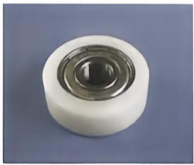
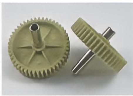
- Clearance Fit: Shaft is smaller than the hole, allowing free movement.
- Interference Fit: Shaft is larger than the hole, requiring force for assembly.
The degree of interference between the shaft and the hole is critical. Insufficient interference compromises joint stability and poses safety risks, while excessive interference increases assembly difficulty and may cause material damage due to overstressing. The retention mechanism depends entirely on friction generated by this elastic deformation. This friction must exceed any external axial or torsional loads applied during operation.
Material elasticity determines the magnitude of this retaining force. Engineers must ensure stresses remain below the yield strength to prevent permanent deformation.
Key Formulas for Force and Stress Calculation
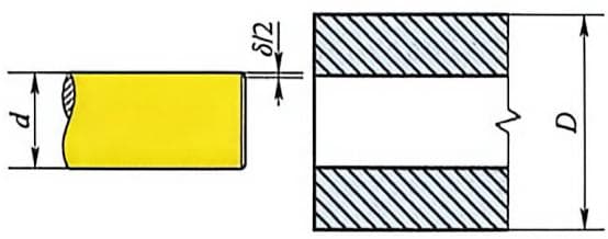
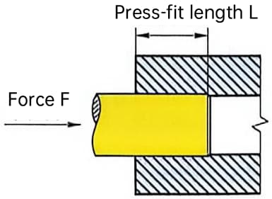
In press fit design, based on the classical theory of thick-walled cylinders, the correct interference $\delta$ between parts must be calculated. The assembly force calculations depend on the coefficient of friction and the contact area.
The interference $\delta$ is calculated as:
$$
\delta = \frac {\sigma_ {\mathrm{D}} d}{W} \left(\frac {W + \nu_ {\mathrm{D}}}{E _ {\mathrm{D}}} + \frac {1 – \nu_ {\mathrm{d}}}{E _ {\mathrm{d}}}\right)
$$
Where $W$ is a dimensionless parameter related to the geometric dimensions of the shaft and hole:
$$
W = \frac {1 + \left(\frac {d}{D}\right) ^ {2}}{1 – \left(\frac {d}{D}\right) ^ {2}}
$$
| Parameter | Symbol | Definition/Typical Consideration |
|---|---|---|
| Interference | $\delta$ | mm |
| Design Stress | $\sigma_{\mathrm{D}}$ | MPa, typically < 20%–25% of short-term tensile yield stress |
| Hub Outer Diameter | $D$ | mm |
| Shaft Diameter | $d$ | mm |
| Hub Modulus | $E_{D}$ | MPa (Hole material) |
| Shaft Modulus | $E_{d}$ | MPa (Shaft material) |
| Hub Poisson’s Ratio | $\nu_{D}$ | Hole material |
| Shaft Poisson’s Ratio | $\nu_{d}$ | Shaft material |
Poisson’s ratio accounts for lateral expansion under axial compression. Ignoring this factor leads to underestimating the required assembly force.
The press fit assembly force $F$ is given by:
$$
F = \mu p A = \mu p \pi d L
$$
Where:
- $\mu$: Coefficient of friction
- $L$: Axial length of the fit
- $p$: Contact surface pressure, calculated as $p=\sigma_{D}/W$
The torque $T$ that can be transmitted is:
$$
T = F \frac {d}{2}
$$
Accurate stress prediction prevents hub failure during high-volume manufacturing. Always verify calculations against material yield limits. For long-term applications, the design stress value should be kept at a relatively low level to minimize stress relaxation and avoid premature failure risks such as sliding or cracking.
Establishing Precise Dimensional Tolerances
Select appropriate ISO tolerance classes such as H7/p6 for standard medium-duty fits. These standards define acceptable deviation limits for both shafts and holes.
- Maximum Interference: Worst-case scenario for assembly force.
- Minimum Interference: Worst-case scenario for slip resistance.
Surface roughness significantly reduces effective interference because peaks flatten during assembly. A common rule of thumb subtracts $2 \times (R_{a,shaft} + R_{a,hole})$ from the geometric interference.
Statistical tolerance analysis ensures consistent quality in mass production. Root Sum Square (RSS) methods predict realistic assembly yields better than worst-case scenarios. During assembly, particularly when the hub is pushed over a shoulder on the shaft, the interference (and corresponding strain level) increases significantly in a very short time. For such short-term assembly interference calculations, acceptable short-term stress (or strain) values are typically used as references.
Software Tools and Simulation for Accuracy
Finite Element Analysis (FEA) software predicts complex stress distributions in non-uniform geometries. It identifies stress concentrations that analytical formulas might miss.
Excel-based templates offer rapid initial estimates for standard cylindrical parts. These tools streamline the iterative design process before committing to detailed simulations.
| Tool Type | Best Use Case | Limitation |
|---|---|---|
| Analytical Excel | Quick sizing, standard shapes | Assumes uniform geometry |
| FEA Simulation | Complex hubs, multi-material | High computational cost |
Digital twins validate manual calculations against real-world sensor data. This feedback loop improves future design accuracy and reduces prototype iterations. Combining analytical methods with simulation ensures robust and reliable press fit designs. Always correlate simulation results with physical testing for critical applications.
Critical Design Guidelines for Plastic Press Fits
Material-Specific Challenges in Polymers
Theoretically, press fits can be used with any thermoset or thermoplastic material. However, in practice, press fit technology is significantly easier to apply to plastics with better toughness.
- Brittle Plastics: Rigid, glassy plastics like phenolic resins or PS have fracture strain values less than 1.0%. The usable design strain, especially in long-term applications where stress relaxation may occur, should not exceed 10% – 40% of this fracture strain value. Consequently, the difference between the hub inner diameter and the shaft outer diameter may be smaller than the combined manufacturing tolerances.
- Tough Plastics: When using tougher plastics such as unreinforced PE, PA, or POM, the design strain value is sufficiently large (relative to combined manufacturing tolerances), making press fit a practical assembly method.
Fillers significantly alter mechanical properties and press fit performance. Glass-filled resins provide higher stiffness but reduce ductility, increasing the risk of brittle fracture during assembly.
| Polymer Type | Typical Creep Resistance | Assembly Risk |
|---|---|---|
| Amorphous (Unfilled) | Low | High Cold Flow |
| Semi-Crystalline (Unfilled) | Moderate | High Shrinkage |
| Glass-Filled (30%) | High | Brittle Fracture |
Managing Thermal Expansion Mismatches
Plastics have a Coefficient of Thermal Expansion (CTE) 5 to 10 times higher than most metals. This mismatch generates significant internal stresses during temperature fluctuations.
- CTE Differential: A typical plastic CTE is $80-100 \times 10^{-6}/^\circ C$, while steel is $\approx 12 \times 10^{-6}/^\circ C$.
- Operational Range: Design calculations must account for the full operating temperature range, not just ambient conditions.
When plastic materials are exposed to permanent stress, the result is creep, meaning the force applied by the press fit decreases over time, though not necessarily to a large extent. Press fits must also consider the manufacturing tolerances of the shaft and hole to ensure feasibility in extreme cases. When joining different materials, temperature rises change the interference between parts. Remember that the effect of creep is greater at high temperatures.
Thermal cycling can lead to stress cracking or loss of interference fit. Selecting material pairs with closer CTE values or designing flexible housing features mitigates these risks.
- Use low-CTE plastics like PPS or LCP for high-temperature metal inserts.
- Incorporate expansion slots in the plastic hub to absorb thermal strain.
Allowable Stress Limits and Safety Factors
Designers must distinguish between short-term yield strength and long-term allowable stress. For long-term press fit applications, the choice of tensile stress value depends on the stress relaxation characteristics of the plastic. Typically, this value is less than 20% – 25% of the material’s short-term tensile yield stress.
- Safety Factors: Apply a safety factor of 2.0 to 4.0 for brittle plastics like PS or SAN.
- Strain Limits: Keep assembly strain below 1-2% for unreinforced plastics to prevent immediate failure.
Time-dependent stress relaxation reduces the holding force over the product’s lifecycle. Initial interference must be calculated to ensure sufficient retention after stress decay. To minimize stress relaxation and avoid premature failure risks such as sliding or cracking, the design stress value for long-term applications should be kept at a relatively low level.
| Condition | Recommended Max Strain | Notes |
|---|---|---|
| Short-Term Assembly | < 2.0% | Avoids immediate cracking |
| Long-Term Service | < 0.5% – 1.0% | Accounts for creep relaxation |
| Glass-Filled Resins | < 0.3% | Low ductility requires caution |
Geometric Design Optimizations for Plastics
Hub wall thickness is critical to prevent bursting during insertion. A general rule is to maintain a wall thickness at least 1.5 times the shaft diameter for standard resins.
- Stiffness Enhancement: Use radial ribs instead of solid walls to increase hoop strength without adding excessive mass.
- Stress Relief: Incorporate relief grooves at the base of the hub to reduce stress concentration factors.
One method to address creep problems in shaft and hub press fits is to provide straight knurling on the metal shaft. The plastic hub material cold flows into the knurling grooves, creating a certain degree of mechanical interference between the parts. Since straight knurling increases the joint’s surface area, the friction effect is also greater.
Chamfers and lead-in angles facilitate easier assembly and reduce surface damage. A lead-in angle of 15-30 degrees is recommended for soft or semi-crystalline materials.
- Relief Grooves: Add a 0.5mm deep groove at the hub entrance to allow material displacement.
- Lead-In Chamfer: Use a 20-degree chamfer to guide the insert and minimize initial spike stress.
Troubleshooting Common Failures and Exploring Alternatives
Diagnosing Loose Joints and Retention Loss
Insufficient interference often stems from molding variations rather than design errors. Check for shrinkage deviations exceeding ±0.2% in semi-crystalline materials like POM or PP.
- Verify mold temperature consistency, as fluctuations of ±5°C can alter part dimensions significantly.
- Measure actual shaft diameters against hub bores using calibrated micrometers to confirm tolerance stack-ups.
Wear and abrasion reduce retention force by smoothing surface textures over time. This is critical in applications with frequent thermal cycling or vibration.
Environmental exposure can cause plasticizers to leach out, leading to dimensional instability. Store components in controlled environments below 60% relative humidity to prevent moisture absorption in hygroscopic resins like Nylon 6/6.
| Failure Mode | Primary Cause | Diagnostic Check |
|---|---|---|
| Loose Fit | Excessive Shrinkage | Measure post-mold dimensions after 24h stabilization |
| Surface Wear | Abrasive Dust | Inspect mating surfaces for micro-scratching |
| Dimensional Drift | Moisture Absorption | Weigh parts before and after drying cycle |
Preventing Cracked Hubs and Component Fracture
Fracture patterns reveal the root cause of failure during assembly. Radial cracks originating from the bore indicate excessive hoop stress during insertion.
- Look for stress whitening in polycarbonate or ABS parts, which signals yield point exceedance.
- Analyze fracture surfaces under magnification to distinguish between slow-crack growth and instantaneous brittle failure.
Rapid assembly speeds generate heat and spike stress levels in brittle plastics. Limit insertion rates to under 50 mm/s for unfilled engineering thermoplastics.
Internal stresses from injection molding weaken the hub structure before assembly even begins. For hubs molded with multiple point gates or internal spoke gates, this is a particular concern as it creates weld lines perpendicular to the direction of tensile stress. In press fit applications, disk or diaphragm gates are preferred as they eliminate weld lines.
| Design Factor | Risk Level | Mitigation Strategy |
|---|---|---|
| Sharp Internal Corners | High | Add 0.5mm minimum radius at hub base |
| Fast Insertion Speed | Medium | Use pneumatic presses with speed control |
| Weld Lines in Hub | Critical | Relocate gate or use valve-gated molds |
When to Choose Snap-Fits Over Press Fits
Snap-fits require lower initial assembly forces but demand precise tooling for undercut release. Press fits rely on constant friction, requiring higher tonnage presses but simpler mold designs.
- Evaluate the required number of assembly-disassembly cycles; snap-fits degrade after 10-50 cycles depending on material resilience.
- Consider that press fits offer superior vibration resistance without additional locking mechanisms.
Cost-benefit analysis favors snap-fits for high-volume consumer electronics where manual assembly is common. Press fits are more economical for automated lines with existing hydraulic press infrastructure.
Aesthetic considerations often drive the choice, as snap-fits can hide engagement points within seams. Press fits may require visible chamfers or lead-ins that disrupt smooth surface continuity.
| Feature | Snap-Fit | Press Fit |
|---|---|---|
| Assembly Force | Low (Manual possible) | High (Machine required) |
| Reusability | Limited (Fatigue risk) | Poor (Deformation on removal) |
| Tooling Complexity | High (Undercuts/Slides) | Low (Standard cores/cavities) |
Evaluating Adhesives and Mechanical Fasteners as Alternatives
Chemical bonding offers superior reliability when sealing against fluids or gases is required. Cyanoacrylates work well for small ABS parts, while epoxies provide better gap-filling for uneven surfaces.
- Use primers on polyolefins like PP or PE to ensure adhesive wetting and bond strength.
- Account for cure times in production scheduling; UV-cure adhesives allow immediate handling but require line-of-sight access.
Hybrid solutions combining press fits with anaerobic adhesives prevent loosening in high-vibration environments. This approach compensates for minor tolerance variations while maintaining alignment.
Mechanical fasteners like screws or rivets are necessary for high-load structural applications. They allow for non-destructive disassembly but add weight and require boss structures that increase part complexity.
| Method | Best Application | Key Constraint |
|---|---|---|
| Adhesives | Sealing/Irregular Gaps | Surface preparation critical |
| Hybrid (Press+Glue) | Vibration Damping | Dispensing accuracy required |
| Screws/Rivets | High Structural Load | Boss design adds wall thickness |
Best Practices for Manufacturing and Assembly Processes
Surface Finish and Preparation Requirements
Surface roughness directly influences friction coefficients and sealing effectiveness. Target an Ra value between 0.4 µm and 0.8 µm for dynamic seals to balance wear resistance and leak prevention.
Mold release agents can significantly increase assembly force variability by altering surface energy. Residual silicone levels above 50 ppm often cause unpredictable stick-slip behavior during press-fit operations.
Implement ultrasonic cleaning with alkaline solutions to remove organic contaminants effectively. Verify cleanliness using water break tests or contact angle measurements below 10 degrees.
- Texturing Benefits: Micro-dimples reduce galling by trapping debris and breaking vacuum seals.
- Grip Enhancement: Laser etching patterns with 50–100 µm depth improve mechanical interlock for adhesive bonds.
Selection of Assembly Equipment and Tooling
Press selection depends on required force precision and production speed. Servo-electric presses offer ±0.5% force accuracy, whereas pneumatic systems typically vary by ±5% due to air compressibility.
| Press Type | Force Accuracy | Speed | Best Use Case |
|---|---|---|---|
| Servo-Electric | ±0.5% | Medium | Precision press-fits |
| Pneumatic | ±5% | High | High-volume, low-tolerance |
| Hydraulic | ±2% | Low | High-force applications |
Force-displacement monitoring detects defects such as missing components or burrs in real-time. Set tolerance windows based on the golden sample curve with a ±10% deviation limit.
Custom fixtures must restrict all six degrees of freedom to prevent misalignment. Use hardened steel locating pins with H7/g6 fit classes to ensure repeatable part positioning within 0.02 mm.
Lubrication Strategies for Smooth Assembly
Lubricant compatibility is critical to prevent environmental stress cracking in plastics. Avoid aromatic hydrocarbons with polycarbonate; instead, use silicone-based or synthetic ester lubricants.
Dry film lubricants like PTFE coatings provide consistent friction coefficients without attracting dust. Liquid oils may migrate over time, potentially compromising adhesive bonds or electrical contacts.
- Long-term Integrity: Excess lubricant can cause creep deformation in thermoplastics under sustained load.
- Application Control: Spray application should target a coating weight of 0.5–1.0 mg/cm² for uniformity.
Automated spray nozzles ensure consistent coverage compared to manual wiping methods. Validate coating thickness using gravimetric analysis or fluorescence detection systems.
Quality Control and Inspection Techniques
Go/No-Go gauges provide rapid verification of critical dimensions on the production line. Design gauges with wear-resistant carbide tips to maintain accuracy over 100,000 cycles.
Statistical Process Control (SPC) tracks dimensional trends to predict process drift before defects occur. Maintain Cpk values above 1.33 to ensure robust process capability and minimal scrap rates.
Destructive testing validates joint strength for batch acceptance using pull-out or torque tests. Sample one unit per 500 produced to verify that assembly forces meet minimum shear strength requirements.
Non-destructive testing (NDT) methods like ultrasonic inspection detect internal voids or cracks. Use X-ray imaging for complex assemblies where visual inspection cannot verify internal pin placement.
Assessing Suitability for Environmental and Dynamic Conditions
Performance Under Vibration and Dynamic Loads
Vibration induces micro-motions at the interface of press-fit joints. This movement leads to fretting corrosion or abrasive wear over time.
Designers must account for shock loads that exceed static interference pressures. Sudden impacts can cause immediate joint slippage or plastic deformation.
- Damping Strategies: Incorporate elastomeric inserts to absorb kinetic energy.
- Fatigue Evaluation: Use Miner’s Rule to estimate cumulative damage from cyclic loading.
| Factor | Engineering Constraint | Mitigation Strategy |
|---|---|---|
| Vibration Frequency | >50 Hz causes rapid wear | Increase interference fit by 10-15% |
| Shock Load | Peak force > Yield Strength | Add mechanical locking features |
| Fatigue Life | <10^6 cycles | Select high-toughness materials |
Long-Term Reliability in Extreme Temperatures
Plastics exhibit significant changes in mechanical properties outside standard ranges. At sub-zero temperatures, materials like PVC become brittle and prone to cracking.
High temperatures reduce the modulus of elasticity in polymers. This softening leads to a loss of interference pressure and joint loosening.
- Thermal Cycling: Perform tests between -40°C and +85°C to validate stability.
- Material Selection: Use PEEK or PPS for continuous exposure above 150°C.
Engineering plastics must maintain dimensional stability during thermal expansion. Mismatched coefficients of thermal expansion (CTE) between mating parts cause stress concentrations.
Chemical and Environmental Exposure Considerations
Hygroscopic plastics like Nylon 6/6 absorb moisture from the environment. This absorption causes swelling up to 2-3% by volume, altering fit tolerances.
Exposure to solvents or oils can lead to environmental stress cracking. UV radiation degrades polymer chains, reducing tensile strength over time.
| Chemical Agent | Effect on Standard Plastics | Recommended Material |
|---|---|---|
| Water/Humidity | Swelling (Nylon) | PBT or Polypropylene |
| Hydrocarbons | Softening/Cracking | PTFE or HDPE |
| UV Light | Embrittlement | ASA or UV-stabilized ABS |
Protective coatings or O-ring seals isolate sensitive joints from harsh media. These barriers prevent direct chemical contact with the press-fit interface.
Final Feasibility Checklist for Application Success
Review all load cases against the selected material’s data sheet. Ensure environmental factors align with the component’s operational limits.
Confirm compatibility using standardized chemical resistance charts. Verify that no adverse reactions occur with nearby fluids or gases.
- Prototype Validation: Test physical samples under real-world conditions.
- Documentation: Record design assumptions and test outcomes for traceability.
Validating performance early prevents costly failures in production. Comprehensive documentation supports future design iterations and quality audits.